Duet3D Logo Duet3D
    • Tags
    • Documentation
    • Order
    • Register
    • Login

    Help with DWC layer chart

    Scheduled Pinned Locked Moved
    Duet Web Control
    5
    21
    1.1k
    Loading More Posts
    • Oldest to Newest
    • Newest to Oldest
    • Most Votes
    Reply
    • Reply as topic
    Log in to reply
    This topic has been deleted. Only users with topic management privileges can see it.
    • Marco Bonaundefined
      Marco Bona
      last edited by

      Very clear, thanks again for the informations

      droftartsundefined 1 Reply Last reply Reply Quote 0
      • droftartsundefined
        droftarts administrators @Marco Bona
        last edited by

        @Marco-Bona If you don't want to put 'E' in the comment, you could change the G1 Z370 F1200 move to a relative move, because that's the other way RRF will ignore it. While this may cause a move beyond the length of the carriage (eg if the print stops at 100mm, and you move +370mm, it will ask to move to Z470), but if you have your axis limits set correctly, it shouldn't matter, and it will stop at the Z axis limit, which I assume is Z370. eg:

        M117 Finishing Up        ;write Finishing Up
        
        M104 S0                  ;extruder heater off
        M140 S0                  ;bed heater off (if you have it)
        
        G91                      ;relative positioning
        G1 Z370 F1200            ;go to Z+370
        G1 E-1 F300              ;retract the filament a bit, to release some of the pressure
        G1 E-5 F9000             ;retract filament even more
        G90                      ;absolute positioning
        
        G28                      ;homing all axes
        M84                      ;steppers off
        
        M117 Print finished      ;write Print finished
        

        I assume your Z axis homes at maximum Z (Z370) rather than minimum Z (Z0)? If it homes at Z0, you probably only want to home X and Y, not all axes (G28), or the print may strike the nozzle/X axis.

        Ian

        Bed-slinger - Mini5+ WiFi/1LC | RRP Fisher v1 - D2 WiFi | Polargraph - D2 WiFi | TronXY X5S - 6HC/Roto | CNC router - 6HC | Tractus3D T1250 - D2 Eth

        1 Reply Last reply Reply Quote 0
        • Marco Bonaundefined
          Marco Bona
          last edited by

          The origin of the machine where I have the sensor is at Z374, then it is the IR probe that zeroes the axis for the first layer.
          However I corrected the lines in the print file but I continue to have problems with the correct visualization of the layers.
          I also tried to restart the machine but I still have some problems.Layer.png

          droftartsundefined 1 Reply Last reply Reply Quote 0
          • droftartsundefined
            droftarts administrators @Marco Bona
            last edited by

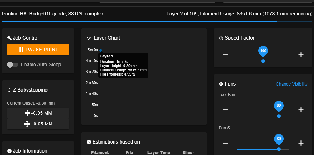
            @Marco-Bona Okay, post another file (perhaps the one shown printing) and I'll take a look. Can you remind me what firmware version you are on, by sending M115 and posting the response.

            Ian

            Bed-slinger - Mini5+ WiFi/1LC | RRP Fisher v1 - D2 WiFi | Polargraph - D2 WiFi | TronXY X5S - 6HC/Roto | CNC router - 6HC | Tractus3D T1250 - D2 Eth

            1 Reply Last reply Reply Quote 0
            • Marco Bonaundefined
              Marco Bona
              last edited by

              @droftarts , The firmware is RRF3.01 RC5 while the version of the DWC is 2.0.7.
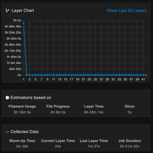
              If it can help, I noticed that at the end of the print the Layer chart is not reset, so in the next print I believe that I continue to display the layer of the previous print.
              The strange thing is that it always stops on the second layer.
              I send you a couple of print files, surely I would have been wrong to insert something in cura even if I don't notice anything strange in the gcode.
              HA_Bridge01F.gcode
              HA_Mast.gcode
              HA_Bridge02.gcode

              Marco Bonaundefined 1 Reply Last reply Reply Quote 0
              • Marco Bonaundefined
                Marco Bona @Marco Bona
                last edited by

                M115
                FIRMWARE_NAME: RepRapFirmware for Duet 2 WiFi/Ethernet FIRMWARE_VERSION: 3.01-RC5 ELECTRONICS: Duet WiFi 1.02 or later + DueX5 FIRMWARE_DATE: 2020-03-27b3
                
                droftartsundefined 1 Reply Last reply Reply Quote 0
                • droftartsundefined
                  droftarts administrators @Marco Bona
                  last edited by

                  @Marco-Bona Actually, I'm mid-print, and experiencing exactly the same thing with 3.01-RC5 and DWC 2.0.7!

                  1fcb6c07-2f2d-4cfe-9c57-d5b078fe232e-image.png

                  I just checked with @dc42, and he has confirmed this is a bug in RRF 3.01-RC5. It counts the start of the print from when the printer was turned on! Will be fixed in next release. If this is important to you, and you don't need changes in RC5, revert to 3.01 RC4 firmware.

                  Ian

                  Bed-slinger - Mini5+ WiFi/1LC | RRP Fisher v1 - D2 WiFi | Polargraph - D2 WiFi | TronXY X5S - 6HC/Roto | CNC router - 6HC | Tractus3D T1250 - D2 Eth

                  Marco Bonaundefined 1 Reply Last reply Reply Quote 0
                  • Marco Bonaundefined
                    Marco Bona @droftarts
                    last edited by

                    @droftarts, Thanks for the reply, you took a heavy weight off me.
                    Viewing the layers is not a problem, I will wait for the next build, but at least I know that my cura file is correct.
                    Thanks again!!

                    1 Reply Last reply Reply Quote 0
                    • chrishammundefined
                      chrishamm administrators
                      last edited by

                      If this issue still persists in DSF 2.1.1 and RRF 3.01-RC6, please provide some more details. Do you leave the web interface running in the background or do you close it, open it back up, and then it is no longer updated? How can you reproduce this?

                      Duet software engineer

                      Marco Bonaundefined 1 Reply Last reply Reply Quote 0
                      • Marco Bonaundefined
                        Marco Bona @chrishamm
                        last edited by

                        @chrishamm, I'm using Duet Wifi for the moment, I don't have DSF.

                        1 Reply Last reply Reply Quote 0
                        • Marco Bonaundefined
                          Marco Bona
                          last edited by

                          If it can help, this morning I noticed that after power on, the DWC print starts from layer 0, performs homing, probing and head cleaning cycle but when the first layer (layer0) starts, it is in progress that the layer2 / XX and does not change.
                          I saw that a new DWC build has come out, tomorrow I install and check it.

                          1 Reply Last reply Reply Quote 0
                          • Marco Bonaundefined
                            Marco Bona
                            last edited by

                            @droftarts, @chrishamm , @dc42, I updated the DWC to 2.1.1, but the problem persists.
                            I found what causes the error, this line in the startup script

                            G1 X-137 E25 F500         ;move to X-137 and extrude 25mm of feed stock
                            

                            creates some problems. It seems that after deleting the first part of the command is working properly

                            G1 E25 F500         ; extrude 25mm of feed stock
                            

                            If it cannot be solved, it is not a problem for me to bleed the nozzle while holding the head steady.
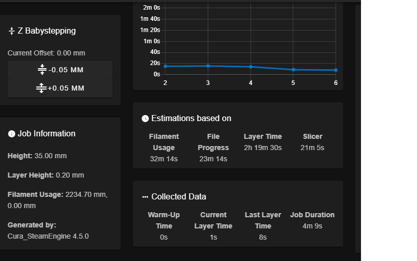
                            I point out that at the beginning of the printing, the estimation of the layers is still incorrect, it is then corrected around the tenth layer.
                            Layer Time.png

                            1 Reply Last reply Reply Quote 0
                            • Phaedruxundefined
                              Phaedrux Moderator
                              last edited by

                              Can you post the entirety of your slicer start gcode?

                              One way to work around it is to move some or all of the slicer start gcode into start.g in the /sys folder. Start.g will be run at the start of every print before any of the sliced gcode file is executed. Same can be done with stop.g and the ending slicer gcode. Stop.g is called by M0 when present. So the slicer end gcode can simply have M0.

                              start.g in combination with other macros called with M98 can allow you to have most of the print prep gcode live outside of the slicer. This has the benefit of making it mostly slicer agnostic so you can use multiple slicers and only need to change the start code in a single place, and it's a workaround for any issues DWC may have when scanning the gcode file.

                              For example, my start.g does a preheat and homing, then passes off to the slicer start gcode to get the heater temps set for printing, then it calls a macro to prime wipe the nozzle and then starts the print. At the end of the print M0 is run to call stop.g which then does a cool down cycle, etc.

                              Z-Bot CoreXY Build | Thingiverse Profile

                              Marco Bonaundefined 1 Reply Last reply Reply Quote 0
                              • Marco Bonaundefined
                                Marco Bona @Phaedrux
                                last edited by

                                @Phaedrux , there he is:

                                M117 Preparing            ;write Preparing
                                G4 S2                     ;delay 2 seconds
                                M140 S60                  ;set bed temperature and move on
                                M141 S0                  ;set heated chamber temperature and move on
                                M104 T0 S195              ;wait for the extruder to reach desired temperature
                                M107                      ;start with the fan off
                                G28                       ;home all axes
                                T0                        ;select tool 0
                                G1 X-23 Y-24 F10000       ;go to the center of bed
                                G1 Z10 F1000              ;E go to Z10
                                M107 P0                   ;turn off leds
                                G30 X-23 Y-24 S-2 H1.915  ;probe current position and ajust Z offset
                                G1 Z40 F1000              ;E go to Z40
                                M106 P0 S1                ;turn on leds
                                T0                        ;reset current tool
                                M584 P4                   ;apply custom setting
                                G1 X-137 Y160 F10000      ;go to X-137 Y160
                                M117 Spray print adhesive ;write Spray print adhesive
                                G4 S2                     ;delay 2 seconds
                                M226                      ;pause
                                M190 S60                  ;wait for the bed to reach desired temperature
                                M109 S205                 ;wait for the extruder to reach desired temperature
                                G1 U130 F10000            ;go to U130
                                G92 E0                    ;reset the extruder position
                                G1 E25 F500               ; extrude 25mm of feed stock
                                G92 E0                    ;reset the extruder position
                                G1 E-4 F5000              ;retract 4mm
                                G1 X-187 F500             ;go to X-187
                                G1 Y165 F500              ;go to Y165
                                G10                       ;retract
                                G1 X-137 F500             ;go to X-137 and clean nozzle
                                G1 XO Y0 U0 F10000        ;go to X0 Y0 U0
                                M584 P3                   ;apply custom setting
                                G21                       ;metric values
                                G90                       ;absolute positioning
                                
                                M117 Print starting       ;write Print starting
                                G4 S2                     ;delay 2 seconds
                                G92 E0                    ;reset the extruder position
                                G1 E4 F500                ;unretract 4mm
                                G11                       ;unretract
                                

                                I was considering doing operations using subprograms.
                                I have to find some time to write and try them.

                                1 Reply Last reply Reply Quote 0
                                • First post
                                  Last post
                                Unless otherwise noted, all forum content is licensed under CC-BY-SA