Endstop do I need a resistor?
-
Usually what you describe for wiring is correct, no resistor needed.. Two "normally closed" in series works fine, I have that in a couple of places. If either one opens, Duet sees that as an endstop hit.
What board, firmware release, and exactly what pins on what port?
Also, full config.g please.
-
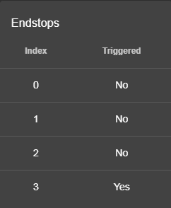
Thanks Danal for the reply I have a Duet Wifi the switches are attached to the Z end stop switch which Index 2.
Board: Duet WiFi 1.02 or later
Firmware: RepRapFirmware for Duet 2 WiFi/Ethernet 2.05 (2019-12-13b1)
Duet WiFi Server Version: 1.23
Duet Web Control 2.0.4;General preferences M111 S0 ; Debug off G21 ; Work in millimetres G90 ; Send absolute coordinates... M555 P2 ; Set output to look like Marlin M83 ; ...but relative extruder moves M208 Y0 Z0 S1 ; set axis minima (adjust to make X=0 and Y=0 the edges of the bed) M208 Y340 Z380 S0 ; set axis maxima (adjust to suit your machine) M208 X0 S1 M208 X360 ;Wifi M550 XXXXXX ; Machine name (can be anything you like) ;M551 XXXXXX ; Machine password (used for FTP connections) M540 P0 XXXXXXXXXX D ; MAC Address ; IP address (0 = use DHCP) M554 Pxxx.xxx.x.x ; Gateway M553 P255.255.255.0 ; Netmask M555 P2 ; Set output to look like Marlin M575 P1 B57600 S1 ; Comms parameters for PanelDue M552 S1 ; start wifi ;Endstops M574 X1 Y2 S1 ; set endstop configuration (X, Y, Z endstops only, at low end XY, high Z, active low) M574 Z2 S1 M581 Z2 S1 T2 ; Z probe M558 P1 R1.0 H10 F200 T1500 X0 Y0 Z0 ;digital piezo sensor, output falls on contact, probing speed, not used to home axes G31 Z1.842 P500 ;sensor is nozzle and debounce value. ; Mesh Levelling M557 X10:360 Y10:320 S50 ;define mesh ;M376 H10 ;taper off after 10mm ;G29 S1 ;load mesh ;Drives M667 S1 ; set to CoreXY mode M569 P0 S1 ; Drive 0 goes forwards (change to S0 to reverse it) M569 P1 S1 ; Drive 1 goes forwards M569 P2 S1 ; Drive 2 goes forwards M569 P3 S0 ; Drive 3 goes forwards M569 P4 S1 ; Drive 4 goes forwards M92 X160 Y160 Z3200 E390 ; Set axis steps/mm Set extruder steps/mm M350 X16 Y16 Z16 E16 I1 ; Set 16x microstepping with interpolation M566 X400 Y400 Z20 E300 ; Set maximum instantaneous speed changes (mm/min) M201 X1000 Y1000 Z100 E6000 ; Set accelerations (mm/s^2) M203 X60000 Y60000 Z200 E20000 ; Set maximum speeds (mm/min) M204 P1000 T4000 ; Set printing and travel accelerations M906 X1000 Y1000 Z1000 E1100 I30 ; Set motor currents (mA)extruder current just enough will click not strip M84 S30 ; Set idle timeout M572 D0 S0.001 ; Set pressure advance S0-off M207 S0.75 R-0.000 F3200 T3200 Z0.0 ; Firmware Retraction M593 F40 ; cancel ringing at 40Hz ; Heaters M305 P0 T100000 B3950 C0 R4700 ; Set thermistor + ADC parameters for heater 0 M143 H0 S150 ; Set temperature limit for heater 0 to 120C M305 P1 T100000 B4725 C7.060000e-8 R4700 ; Set thermistor + ADC parameters for heater 1 M143 H1 S285 ; Set temperature limit for heater 1 to 285C M307 H1 A394.1 C234.5 D3.0 S1.00 V11.8 B0 ; Tools M563 P0 D0 H1 ; Define tool 0 G10 P0 X0 Y0 Z0 ; Set tool 0 axis offsets G10 P0 R0 S0 ; Set initial tool 0 active and standby temperatures to 0C M591 D0 P5 C3 R140:220 E3.0 S0 ; Thermistors and heaters M570 S180 ; Increase to allow extra heating time if needed ; Automatic power saving M911 S10 R11 P"M913 X0 Y0 G91 M83 G1 Z3 E-5 F1000" ; Set voltage thresholds and actions to run on power loss ;Fan config M106 P0 S0 H-1 C"Hotend Fan" M106 P1 S1 I0 F500 H1 T45 C"Parts Fan" M106 P2 T38:42 H100:101:102 C"Board Fan" ;M106 P1 S1 I0 F500 H1 T45 ;M106 P1 T45 H1 ;M106 P0 S0 I0 F500 H-1 ; set fan 2 ;M106 P1 H-1 ; set fan 1 to be gcode controlled ;M106 P1 S0 ; switch off fan 1 at startup (and verify m106 will control fan 1) ; Tool definition ;M563 P0 D0 H1 F1 ; Define tool 0 ;G10 P0 S0 R0 ; Set tool 0 operating and standby temperatures ;*** If you are using axis compensation, put the figures in the following command ;M556 S78 X0 Y0 Z0 ; Axis compensation here M501 ; Run config-override.g T0 ; select first hot end M561 -
@Synapsis said in Endstop do I need a resistor?:
M574 Z2 S1 M581 Z2 S1 T2
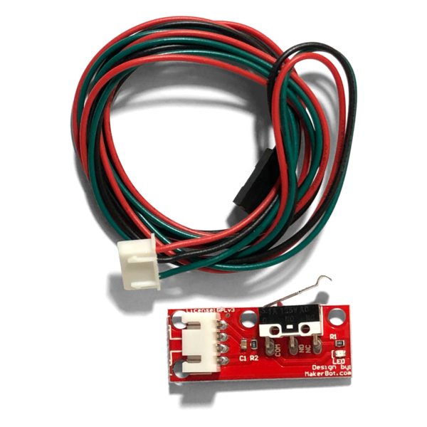
Hmm, that all looks correct. You say these have LEDs on them, those normally have three wires, one ground, one 3.3V, and one sense... how are those connected?
-
Switch 1 Signal pin goes to signal pin on Duet the common goes to signal pin on Switch 2 which the goes to Ground pin on Duet. So I have it going from ground to signal on the board like I read in a post.
-
Aha! Good old makerbot... long story, let's just fix it to work.
Step 1: Parallel the switches. All three wires. Like this:
NOTE DO NOT PLUG THESE IN YET, see step 2.
Switch A:
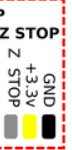
- Ground (black) to ground on Duet (black pin in diagram below)
- Vin (red) to +3.3V on Duet (middle yellow pin)
- Green to Duet XYZ stop (grey pin in diagram below)
Switch B:
- Ground (black) to ground on Duet (black pin in diagram below)
- Vin (red) to +3.3V on Duet (middle yellow pin)
- Green to Duet XYZ stop (grey pin in diagram below)
You can "Y" the wires together any way you wish. Crimp in to same connector splice, etc.
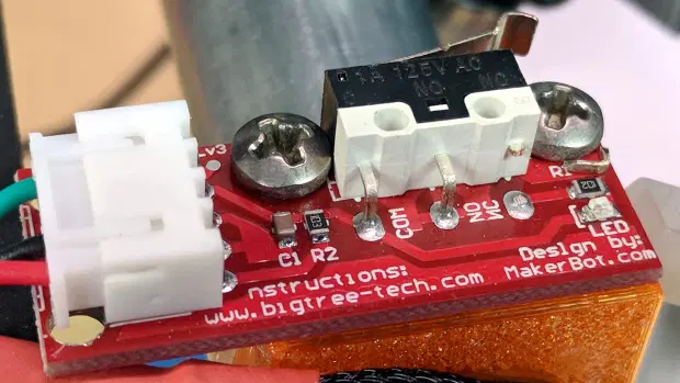
Step2: Modify BOTH endstop boards as follows:
Clip out the "NC" connection on the physical switch.
Now you should get what you want. Either switch pressed (or both) will make index 2 go "Yes".
Delta / Kossel printer fanatic
-
@Synapsis said in Endstop do I need a resistor?:
... the past a couple of times the Z-probe wasn't working the bed would crash into the nozzle ...
On my printer I have mechanism hard stops such that the bed cannot push the nozzle more then a few mm which can absorbed by the flex of the X rods. Saved me a few times.
-
With these makerbot boards you can remove all of the surface mount components then get a normally closed switch across the outer two connections on the plug.
The surface mounts can be tricky to remove with a soldering Iron and will likely get destroyed doing so.
-
With the boards as is there could be additional fault diagnosis on the boards but the added complexity would rarely be used.
i.e. Open circuit is a fault, close circuit is switch not triggered, the voltage that causes a dim LED is switch triggered.
Thinking on it further this could be an SPI board to achieve that...
Edit; could an SPI board be checked regularly for an ok signal?
-
@Danal said in Endstop do I need a resistor?:
......
Clip out the "NC" connection on the physical switch.
....Thanks for the fix but one question will it be a NO or NC because if I cut the NC
wouldn't it become a NO?zapta 16 Apr 2020, 06:33
I have 2 linear guides on a 20x20 profile so I have no flex what so ever only thing to move it the head mount and head.
") but like you were saved I wasn't saved .
but like you were saved I wasn't saved . 
DocTrucker 16 Apr 2020, 08:57
I had tried with a tester and I have a closed circuit until I would press one of the two switches so thought the board had a internal resistor to detect it as NC.
-
OK so I see where I was mislead or better misread. On the Wiki Connecting endstop switches I read
"Microswitch
This applies to a bare microswitch, not to a microswitch on a board with a LED.
this i what i didn't see.Duet WiFi, Duet Ethernet and Duet Maestro: connect the switch between GND and STP/IN. These are the outer 2 pins of the 3-pin connector. Note: this is not the same as on RAMPS."
-
@Synapsis if you clip the leg like picture you will get a normally open switch, which is a poor choice for a limit switch as it can't detect the most likely failure of a wire breaking or plug pulling out. I remove all of the surface mount components and the outer two connections on the plug behave as normally closed, which is what you want for a limit switch or z-probe.
Running 3 P3Steel with Duet 2. Duet 3 on the shelf looking for a suitable machine. One first generation Duet in a Logo/Turtle style robot!
-
@DocTrucker said in Endstop do I need a resistor?:
@Synapsis if you clip the leg like picture you will get a normally open switch, which is a poor choice for a limit switch as it can't detect the most likely failure of a wire breaking or plug pulling out. I remove all of the surface mount components and the outer two connections on the plug behave as normally closed, which is what you want for a limit switch or z-probe.
Exactly what I thought, as I do want NC. Do you have a photo of how you did it?
Thanks for your help.
-
@DocTrucker said in Endstop do I need a resistor?:
@Synapsis if you clip the leg like picture you will get a normally open switch,
No, he won't. The circuit effectively inverts the behavior (note, not logic, behavior).
And if he wires in parallel and doesn't clip it, triggering one switch WILL CROWBAR THE OTHER SWITCH, which could potentially damage the board to which they are plugged in.
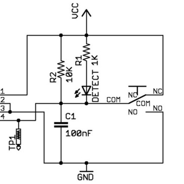
Think of two of these in parallel, with one of them triggered. That combination just connected VCC DIRECTLY to ground.
Delta / Kossel printer fanatic
-
@DocTrucker said in Endstop do I need a resistor?:
I remove all of the surface mount components and the outer two connections on the plug behave as normally closed, which is what you want for a limit switch or z-probe.
This will ALSO work. By removing ALL the components, this is a simple switch again, and you are absolutely correct, the outer two wires (com and nc) are what you want.
In fact, I'd remove the switch from the board.
AND... In that case the wiring is sequential, not parallel.
- Duet GND to outer terminal (doesn't matter which) on switch A
- Other outer of switch A to outer on switch B
- Other outer of B to TRIG on Duet
Forms a big "loop" between Trig and Gnd.
-
Thanks Danal and DocTrucker for the help.
-
Ok one last question, I hope, end stops now working ok took out the R1 and R2 and it works, question now if I use M581 Z2 S1 T0 C0 this will send a M112 and reset the board if I use T1 I would get a pause (which I want ) but this only works while printing?
I didn't want to use a trigger because there maybe a little delay before executing the command.
Am i forced to use T0? -
@Synapsis said in Endstop do I need a resistor?:
Ok one last question, I hope, end stops now working ok took out the R1 and R2 and it works, question now if I use M581 Z2 S1 T0 C0 this will send a M112 and reset the board if I use T1 I would get a pause (which I want ) but this only works while printing?
I didn't want to use a trigger because there maybe a little delay before executing the command.
Am i forced to use T0?What is your goal? When homing, the printer will stop itself if it hits either of those endstops.
Do you want it to pause if it hits one while printing? Or something else?
Delta / Kossel printer fanatic
-
@Danal said in Endstop do I need a resistor?:
Think of two of these in parallel, with one of them triggered
ouch; is that a common schematic for all those endstops with leds?
-
@bearer said in Endstop do I need a resistor?:
@Danal said in Endstop do I need a resistor?:
Think of two of these in parallel, with one of them triggered
ouch; is that a common schematic for all those endstops with leds?
Yeah, ouch indeed. I'm glad you see it as well.
AFAIK it is common to anything that has that "Design by MakerBot" in one corner. Including BigTreeTech and several other retail/channel brands. Meaning, VERY common.
-
@Danal said in Endstop do I need a resistor?:
@Synapsis said in Endstop do I need a resistor?:
Ok one last question, I hope, end stops now working ok took out the R1 and R2 and it works, question now if I use M581 Z2 S1 T0 C0 this will send a M112 and reset the board if I use T1 I would get a pause (which I want ) but this only works while printing?
I didn't want to use a trigger because there maybe a little delay before executing the command.
Am i forced to use T0?What is your goal? When homing, the printer will stop itself if it hits either of those endstops.
Do you want it to pause if it hits one while printing? Or something else?
They are a backup in case during homing the Z-probe for some reason does not work, so I want it to stop the movement of the bed but without having to reset the printer by recycling it off/on for example. There will be one near the two lead screws.