Another BL touch config question: Y-offset this time
-
@jallen810 said in Another BL touch config question: Y-offset this time:
And the second I wired up and attempt to use but BLtouch won't do self-test. But I can get it to manually deploy/retract with M280 P3 S10/90 I1 commands.
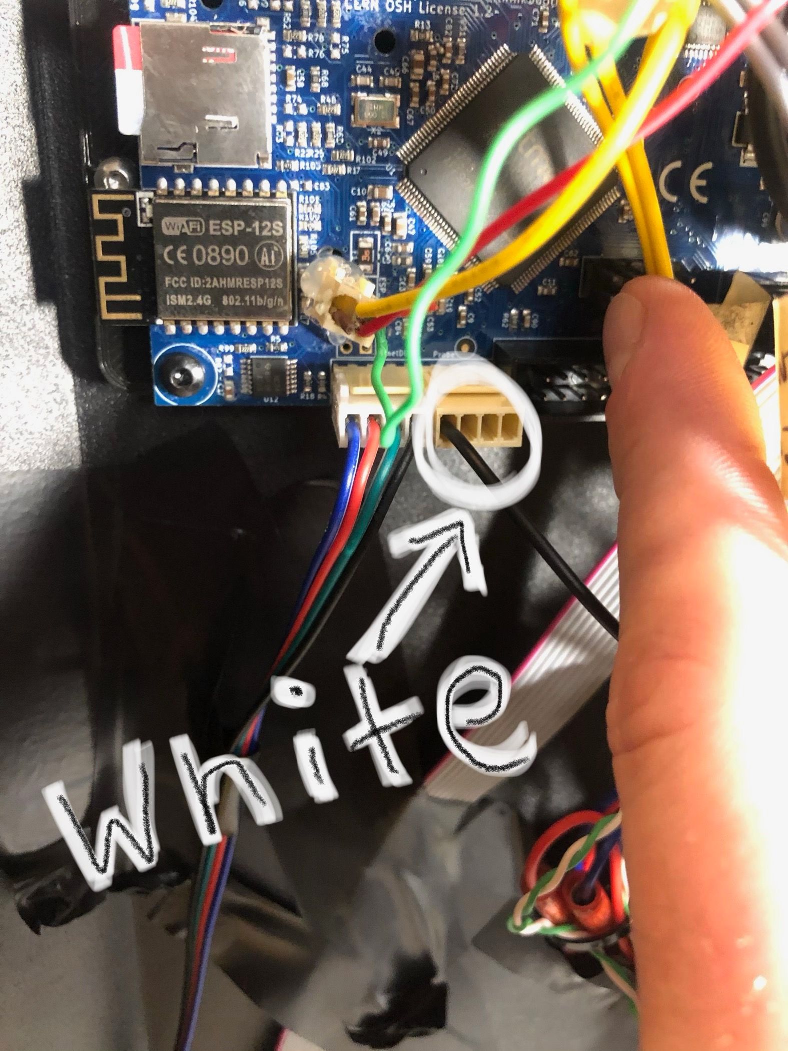
In your first picture it doesn't look like you have any servo wires connected, so it's not going to be able to control the pin like that.
The second photo looks more correct for the Duet Wifi, and you say you're able to control the pin, so that's a good start.
How are you trying to do the self-test? Does it do a self test at power up?
Have you tried testing it's operation yet?
https://duet3d.dozuki.com/Wiki/Test_and_calibrate_the_Z_probe#main
Can you post your current config.g, homeall.g, homez.g, bed.g, deployprobe.g, retractprobe.g, config-override.g files please for verification?
-
@Phaedrux @dc42 The first picture works by running P5 on pin 7 but I want to do it "right" via P9 as you are suggesting.
My biggest concern at the moment is not being able to use all of my bed.
I am attaching all of my sys files in a GoogleDrive folder for you. I very much appreciate all of the deep dive troubleshooting! This is an amazing community!https://drive.google.com/drive/folders/16hlgYO5NkJfsM0njdcNSuSkMSUl3Cbbw?usp=sharing
-
I'll go through your configs and point out anything that seems off.
In config.g your Z axis max speed seems a bit high. If it's set too high it may bind/stall/skip steps. So be sure to test it to see if it's actually a safe speed. 600mm/min (10mm/s) is probably a more reasonable value.
M203 X6000.00 Y6000.00 Z1500.00 E3000.00 ; set maximum speeds (mm/min)On the flip side of that, your Z and E axis jerk values are a bit on the low side which may cause you some issues with mesh compensation and pressure advance, respectively.
M566 X800.00 Y980.00 Z12.00 E180.00 ; set maximum instantaneous speed changes (mm/min)I would recommend Z60 and E2500
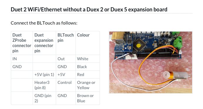
For the BLtouch
M558 P9 H5 F100 T16000  ; (Duet3D method) P=Select Z-probe mode=9 BLtouch. H=DiveHeight abv bed(mm), F=Speed bed moves, T=TravelSpeed btwn pts
G31 P500 X0 Y0 Z0.59               ; P=Z probe trigger value,X&Y=offset for mount relative to nozzle (mm), Z=trigger height "Z-offset"(mm)
M558 T16000 for the travel speed between probe points is higher than your XY axis max speed. It will be limited to 6000mm/min.
Your G31 still doesn't have your probe/nozzle offsets. Based on what you mentioned in your first post it should be X58 Y-36. Without those values the heightmap will be applied incorrectly.
Change G31 P500 to G31 P25
And your trigger height of 0.59mm seems quite low. When the BLTouch is mounted correctly based on the Antclabs manual the base of the probe body should be ~8mm above the nozzle tip which will give a trigger height of ~2mm.
For the mesh grid, in order to maximize the probe points and reachable area we need to account for the probe offset. If you take the axis limits from M208 and subtract the offsets you get the reachable area. Round up or down a bit and then choose a spacing that divides into the range evenly.
M557 X0:225 Y45:300 S45would becomeM557 X60:300 Y0:260 S20Then when you use G29 it should map the entire reachable area of the bed with a 20mm spacing.
For your fan arrangement, it's recommended to use Fan0 as the part cooling fan because the slicers generally don't allow you to choose a fan number. So it makes sense as the default. Plus, the Duet defaults to using the Fan1 port as the heatsink and it will spin up the fan immediately at power on just in case you did a reset with the hotend hot, it can help prevent jams from heat creep.
M106 P1 C"PartCool_FAN0" S0 I0 F500 H-1              ; set fan 1 name, value, PWM signal inversion and frequency. Thermostatic control is turned on
M106 P0 C"HeatSink_FAN1" S1 I0 F500 H1 T45            ; set fan 2 name, value, PWM signal inversion and frequency. Thermostatic control is turned off
To change it to match the expected defaults just swap the fan ports and change then swap P1 and P0 in config.
This also makes more sense because your current tool definition selects fan0 as the tool fan.
M563 P0 S"HOTEND0" D0 H1 F0The rest of your config looks ok.
As for the BLTouch, answer my previous questions as I'm not sure what is or isn't working.
@Phaedrux said in Another BL touch config question: Y-offset this time:
How are you trying to do the self-test? Does it do a self test at power up?
Have you tried testing it's operation yet?
https://duet3d.dozuki.com/Wiki/Test_and_calibrate_the_Z_probe#main -
@Phaedrux i will make these changes tomorrow. In the meantime to answer your question about BL self-test, I mean the power up sequence that the BLtouch does when m/c is powered on. It will cycle the probe 2-3 times then retract and give a solid red light, if wired correctly. If I wire it as you recommend, this does not happen. If I try to do a G30, the probe will not extend and thus will plunge into bed.
But if I wire it like BeTrue3D recommends, it works fine. -
You can use any free heater pin on the expansion connector to connect the servo wire, you just need to specify which one in the P parameter of the M280 commands in deployprobe.g and retractprobe.g. So try connecting the servo control wire as in the your first photo, and the other BLTouch wires as in the second. If that gives you the self test at power up, then change the M307 and M280 commands to refer to the correct heater pin (M307 H parameter, and M280 P parameter). I think that is Heater 7 for that alternative servo wire connection.
-
@jallen810 said in Another BL touch config question: Y-offset this time:
If I wire it as you recommend, this does not happen.
I suspect a bad wire connection based on your photo.
-
Okay. I made all of these changes to my config files (see them here) and when I boot up I get the BLtouch doing the self-test when I power on.
Now I have a problem with the probe deploying the probe when I try to:
1.) Calibrate the Z-offset per this page's instructions, I'm referring to M401/2 and G30
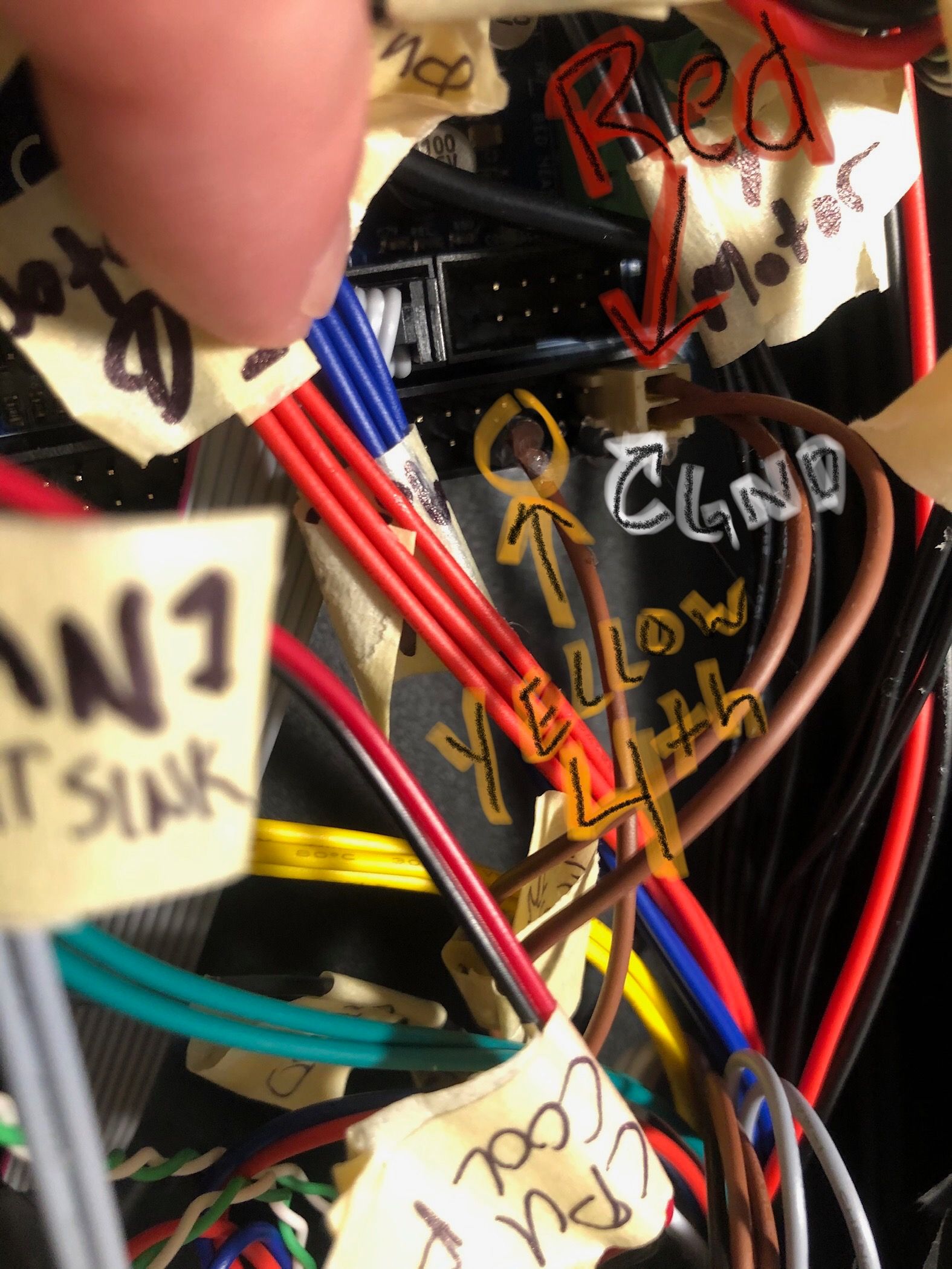
2.) Manually (with macro's in G-Drive link) try to deploy/retract/self-test/resetBelow Pic is EXACTLY how my system is currently wired. I'm not changing that again, to avoid confusion in future.
The connections are solid dupont-connections that are hot-glued in place
Here is my actual wiring:
(
-
Deploy probe isn't working because you have
I0when it should beI1M280 P3 S10 I0 -
@Phaedrux yeah I was playing with the "I" value, forgot to change that back. Just tried again with M280 P3 S10 I1 and that doesn't work either..
Should M401 also do the same thing? If so, it doesn't work either -
This indicates an open circuit connection in the yellow wire.
M401 and M402 commands execute the deploy and retract macros and allow the firmware to keep track of the state of the pin.
-
@Phaedrux Great... lol YAY more wire tracing... just what I wanted. Thanks Phaedrux.
-
@Phaedrux
Okay. Everything is finally working with probe.One last, hopefully, easy question regarding fans.
Problem: Both my Heatsink fan & Part Cooling fans come on when I power up.
Facts: Heatsink is plugged physically into Fan1 port
AND my Part Cooling fan, plugged into Fan0 portAs I've learned, only the heatsink fan should come on in this situation. I played around trying to make Fan0 be thermostatically controlled >45C but it doesn't seem to want to be... Here is the fan & tool related stuff in my config. Please oh wise one, tell me where I am being a bonehead.
;-----Fans-----------------------------------------------------------------
M106 P0 C"PartCool_FAN0" S0 I0 F500 H1 T45
M106 P1 C"HeatSink_FAN1" S1 I0 F500 H-1;-----Tools-----------------------------------------------------------------------------------------
M563 P0 S"HOTEND0" D0 H1 F0
G10 P0 X0 Y0 Z0
G10 P0 R0 S0 -
@jallen810 said in Another BL touch config question: Y-offset this time:
M106 P0 C"PartCool_FAN0" S0 I0 F500 H1 T45
M106 P1 C"HeatSink_FAN1" S1 I0 F500 H-1You've got the thermostatic part mixed up. It should be
M106 P0 C"PartCool_FAN0" S0 I0 F500 H-1 M106 P1 C"HeatSink_FAN1" S1 I0 F500 H1 T45 -
@Phaedrux said in Another BL touch config question: Y-offset this time:
M106 P1 C"HeatSink_FAN1" S1 I0 F500 H-1
What if that didn't work? I confirmed polarity and port. It is wired correctly. Is there another file that might contain something from the RRF configuration tool that could be over-riding?
EDIT: I just tied commenting out all of the fan allocations just to see if that would kill all of the fans, but instead all of them still came on...
This would seem to me that there is a wiring issue on my end but the fans are plugged to the right ports...