Duet3D Logo Duet3D
    • Tags
    • Documentation
    • Order
    • Register
    • Login

    New power output for toolboard

    Scheduled Pinned Locked Moved
    Duet Hardware and wiring
    2
    9
    360
    Loading More Posts
    • Oldest to Newest
    • Newest to Oldest
    • Most Votes
    Reply
    • Reply as topic
    Log in to reply
    This topic has been deleted. Only users with topic management privileges can see it.
    • eduardundefined
      eduard
      last edited by

      Hello, may I have some help to control a new power output on duet3 Tool Board 1LC v0.6 for a second heating element?

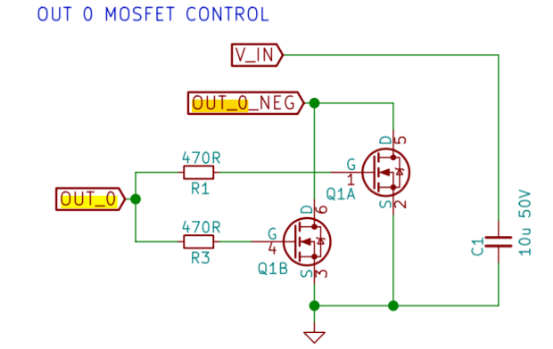
      I build a mosfet darlington based on OUT_0 in toolboard schematic and connected to the tool board ATSAMC21G18A pin PA16(25).

      My question is, how can I address this pin and add a function to it?

      Screenshot 2020-05-17 09.18.18.png

      Thank you for the help.

      1 Reply Last reply Reply Quote 0
      • dc42undefined
        dc42 administrators
        last edited by dc42

        You would need to change the line for PA16 in file src/Config/TOOL1LC_V06.h. Giving the pin a name such as "out3" should be sufficient.

        If the pin is intended for a heater, you might want to add a 10K pulldown resistor between PA16 and ground, to ensure that the mosfets are off when the board starts up. We've added a similar resistor on OUT_0 in later production tool boards.

        Duet WiFi hardware designer and firmware engineer
        Please do not ask me for Duet support via PM or email, use the forum
        http://www.escher3d.com, https://miscsolutions.wordpress.com

        1 Reply Last reply Reply Quote 1
        • eduardundefined
          eduard
          last edited by

          Thank you @dc42, I'll give it a try. I'll add the 10k pulldown for OUT_0 as well.

          I look up but did not find the kicad pcb design on git. It is exist? I'll looking for a better trace for add the resistors than the uC pin.

          dc42undefined 1 Reply Last reply Reply Quote 0
          • eduardundefined
            eduard
            last edited by

            @dc42 there is an opportunity to drive an RC servo (PWM) from the toolboard? I can modify it and connect to the uC pin if needed.

            dc42undefined 1 Reply Last reply Reply Quote 0
            • dc42undefined
              dc42 administrators @eduard
              last edited by

              @eduard said in New power output for toolboard:

              @dc42 there is an opportunity to drive an RC servo (PWM) from the toolboard? I can modify it and connect to the uC pin if needed.

              The IO_0_OUT pin is PWM capable, it already gets used to control a BLTouch. However, the on-board 5V regulator doesn't have much spare output capacity, so a servo will need external 5V power. Additionally, when servos decelerate they pump energy back into the power rail, which causes the voltage to rise; and this could easily damage the microcontroller if you powered the servo from the tool board.

              Duet WiFi hardware designer and firmware engineer
              Please do not ask me for Duet support via PM or email, use the forum
              http://www.escher3d.com, https://miscsolutions.wordpress.com

              1 Reply Last reply Reply Quote 1
              • dc42undefined
                dc42 administrators @eduard
                last edited by

                @eduard said in New power output for toolboard:

                I look up but did not find the kicad pcb design on git. It is exist? I'll looking for a better trace for add the resistors than the uC pin.

                PCB layout is not on github yet. I checked in KiCad and there are no traces connected to any of the unused pins 25-28 of the MCU. I've made a note to add pads for one or more of these pins in the next PCB revision.

                Duet WiFi hardware designer and firmware engineer
                Please do not ask me for Duet support via PM or email, use the forum
                http://www.escher3d.com, https://miscsolutions.wordpress.com

                1 Reply Last reply Reply Quote 1
                • eduardundefined
                  eduard
                  last edited by

                  Thank you for your answer, I'll keep in mind while designing the servo control pcb. Perhaps a supressor diode will do the job.

                  How can I drive the servo from G-code? The is already a macro for servo drive? (0-180 degree control, or mapping command)

                  dc42undefined 1 Reply Last reply Reply Quote 0
                  • dc42undefined
                    dc42 administrators @eduard
                    last edited by

                    @eduard said in New power output for toolboard:

                    How can I drive the servo from G-code? The is already a macro for servo drive? (0-180 degree control, or mapping command)

                    See the M280 command.

                    Duet WiFi hardware designer and firmware engineer
                    Please do not ask me for Duet support via PM or email, use the forum
                    http://www.escher3d.com, https://miscsolutions.wordpress.com

                    1 Reply Last reply Reply Quote 0
                    • eduardundefined
                      eduard
                      last edited by

                      Great, thank you!

                      1 Reply Last reply Reply Quote 0
                      • First post
                        Last post
                      Unless otherwise noted, all forum content is licensed under CC-BY-SA