Duet Maesto Stepper Driver Expansion Schematic
-
You said you have two expansion boards. Is P5 noisy on both of them?
-
@dc42 I just did the exercise and switched the expansion board. Same result.
I thought that it might be the cables. So I decided to switch those too. Also, I twisted the pairs, but that also did not have an impact.
Some more insight I have found: only one of the two current paths is affected. Output 1 of P5. Output 2 is fine. Somehow the upper (well, upper depends on your point of view, but it is clear what I mean
 ) part of the sine wave gets a bit chopped of output 1.
Consequently, the two coils in the motor see a different current and hence are driven assymetrically. For me, it now looks like a bug (although it would be nice if someone else could try the same).
https://duet3d.dozuki.com/Wiki/Dual_Stepper_Driver_Expansion_Module
-
Okay. So I split up both of my expansions (one of which already had a groove and was easy, the other one was more work) and installed both "P6" to the Maestro.
Everything is running fine now!

Well, this concludes it for me. I have two leftover P5 - if someone is interested.

-
Replacing the controller on a Chinese IDEX printer with a Duet 2 Maestro + Stepper Driver Expansion and I've run into this same problem. P5 is VERY noisy when it switches to SpreadCycle mode. Sounds almost like the stepper is stalled and you can feel the carriage vibrate while moving. (double checked the wiring, haven't crossed anything...) I'm using the same stepper motor on the P0 channel, and P0 is silent.
Anyone figured out what's wrong with the P5 stepper driver on the expansion? Does it need some components replaced? (wrong Capacitor or resistor somewhere?)
For now I've worked around it by setting the "V" parameter to 25 so it says in Stealth chop for most moves. It also got better when I swapped the X1 and X2 motors and wires. The motors are the same part number but, the X2 motor has longer wires.
M569 P5 S1 D3 V25 ; physical drive 5 goes forwards E2 (Very noisy!) -
@BotLawson I think there is a flaw with the design of the expansion. Even P6 produces slightly worse results than the internal steppers.
As for P5, there might be a way to fix it by comparing the layout of P5 with P6 and find the difference. Still missing this file though.
From looking at the PCB, there is not much to observe between the two...
-
Do the passive components around the TMC2224 chip look identical on both parts of the boards that you have?
-
@dc42 from what I could tell, yes. But that really does not mean much.
The layout of output 1 (which is the output that generates the problem) looks a bit different, but I am not sure if this really would be a problem. Would be easier to see with the actual layout in a design tool.
-
I do see some differences in the expansion board schematic. The 470pF ESD capacitors on the motor outputs have different voltage ratings. If the Duet 2 has NPO caps while the Expansion has Y5V (or even X7R) this might cause some noise as the higher capacitance capacitor dialectics are non-linear and piezoelectric while the NPO dialectic is nearly ideal.
I'd also look closely at the grounding and parasitics of the current sense resistors on P5. That current wave-form sure looks like the current loop has started to go unstable. Might not need much series inductance to drive it over the edge. (the TMC2224 data sheet even warns about stray inductance on this circuit) Also check the supply decoupling for stray inductance or capacitor dialectic differences as these could can easily couple back into the loop.
-
@BotLawson said in Duet Maesto Stepper Driver Expansion Schematic:
I'd also look closely at the grounding and parasitics of the current sense resistors on P5.
I suspect that's where the problem lies.
-
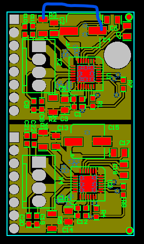
I've managed to obtain the Gerber files for the expansion daughter board, and I think the difference between P5 and P6 can indeed be explained by layout differences - in particular, differences in the ground plane. Here is the top copper layer of the PCB.

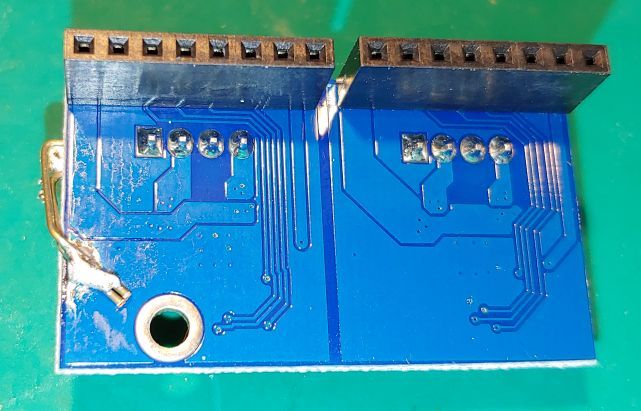
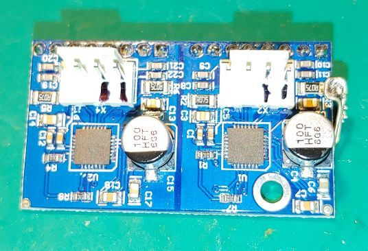
The most significant difference I can see is that in the upper driver, the top (ground) end of sense resistor R3 has to go around a very long path to reach the decoupling capacitors and the ground pad of the chip. You could try adding a wire link as shown between the top end of R3 and either the ground end of the electrolytic capacitor C4 as shown (taking care not to short it against C6) or alternatively looping over the edge of the board to the bottom copper ground plane underneath the ground end of C4.
-
@dc42 Thank you for this analysis. At the moment, I do not have the need to try it out (as I have two P6). But I am sure that others may find it useful!

-


Looking at the layout render, it looks like the culprit is the Vin trace to C6. It cuts off the direct path to ground and forces current from R3 to loop around the outside of the pcb. Personally, I'd put R3 and R2 between the TMC chip and stepper connector and give them 2-4 vias to the ground plane and the thermal die pad of the TMC. The motor phase connections can then sneak under or around the 805 resistor.
-
@BotLawson said in Duet Maesto Stepper Driver Expansion Schematic:
Looking at the layout render, it looks like the culprit is the Vin trace to C6. It cuts off the direct path to ground and forces current from R3 to loop around the outside of the pcb. Personally, I'd put R3 and R2 between the TMC chip and stepper connector and give them 2-4 vias to the ground plane and the thermal die pad of the TMC. The motor phase connections can then sneak under or around the 805 resistor.
Exactly. There is this "unconnected" peninsula to the right of R3/C2. Great job to both of you guys. I guess this fixes it.

-
 undefined droftarts referenced this topic