Duet3D Logo Duet3D
    • Tags
    • Documentation
    • Order
    • Register
    • Login

    Duet Maesto Stepper Driver Expansion Schematic

    Scheduled Pinned Locked Moved
    Duet Hardware and wiring
    4
    27
    1.8k
    Loading More Posts
    • Oldest to Newest
    • Newest to Oldest
    • Most Votes
    Reply
    • Reply as topic
    Log in to reply
    This topic has been deleted. Only users with topic management privileges can see it.
    • T3P3Tonyundefined
      T3P3Tony administrators
      last edited by

      @Wurstkarton got the thumbs up:
      https://github.com/T3P3/Duet/blob/master/Duet_Expansion/Maestro_Expansion/Duet 2 Maestro - Expansion Schematic.PDF

      www.duet3d.com

      Wurstkartonundefined 1 Reply Last reply Reply Quote 0
      • Wurstkartonundefined
        Wurstkarton @T3P3Tony
        last edited by

        @T3P3Tony Thank you! That was quick.

        I'll take a look later.

        1 Reply Last reply Reply Quote 0
        • Wurstkartonundefined
          Wurstkarton
          last edited by

          From the schematic, I do not really see any noteworthy difference. As @dc42 mentioned, it rather might be the implementation in the layout.

          Anyways, I'll use a current probe with an osci this week to assess the differences. I'll come back with what I find.

          1 Reply Last reply Reply Quote 0
          • Wurstkartonundefined
            Wurstkarton
            last edited by

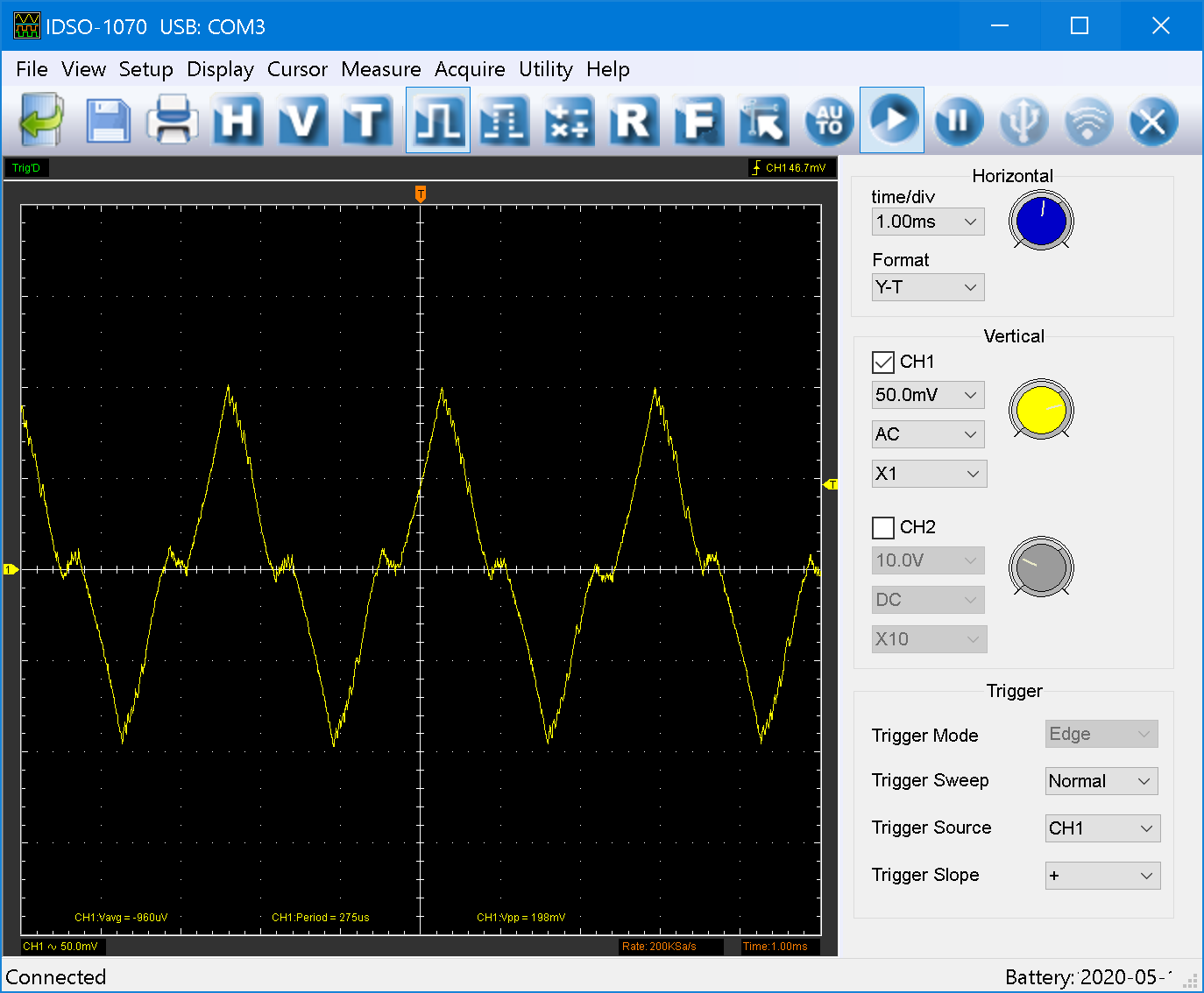
            I performed the analysis and checked the current fed by the drivers into the motors using a scope + current probe attached to a single wire of the motor.

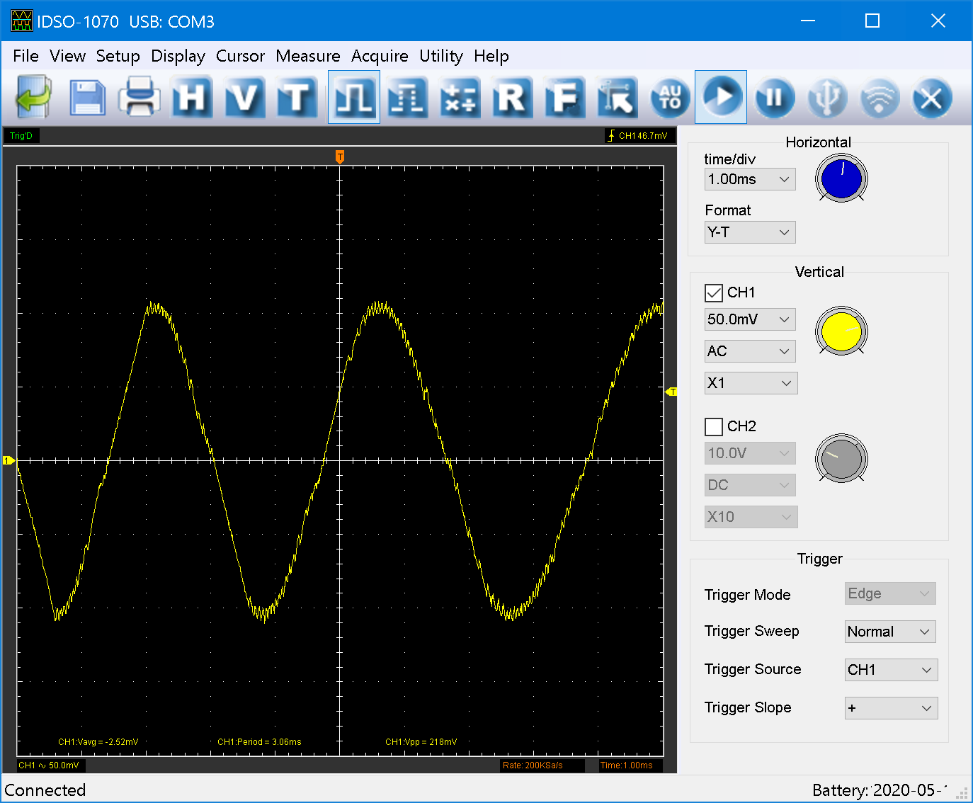
            This is how a onboard driver performs (P4, TBL = 1, different feedrates):

            B1_f300.png
            B1_f1800.png
            B1_f3600.png

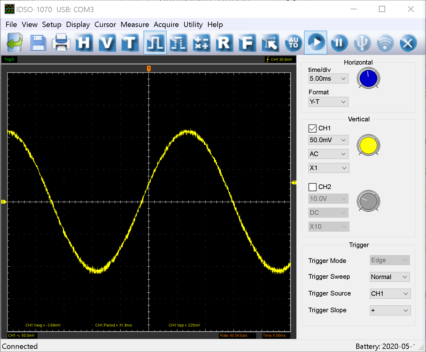
            As can be observed, the waveforms are very smooth. At 60mm/s, you can see that the sine wave gets jagged (which is fine for higher speeds).

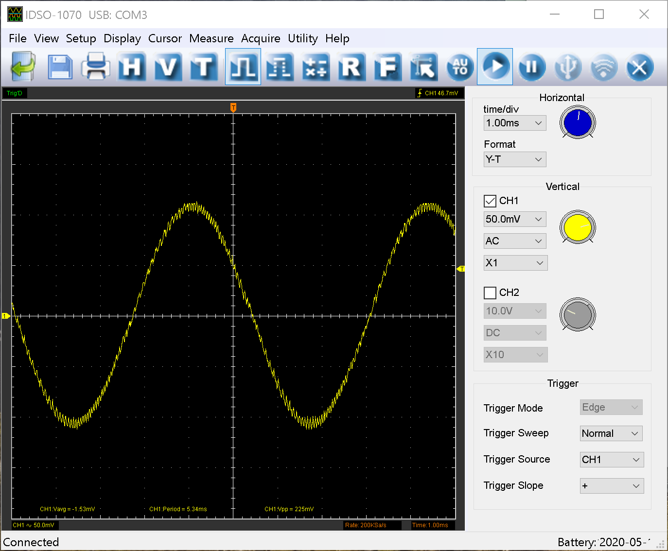
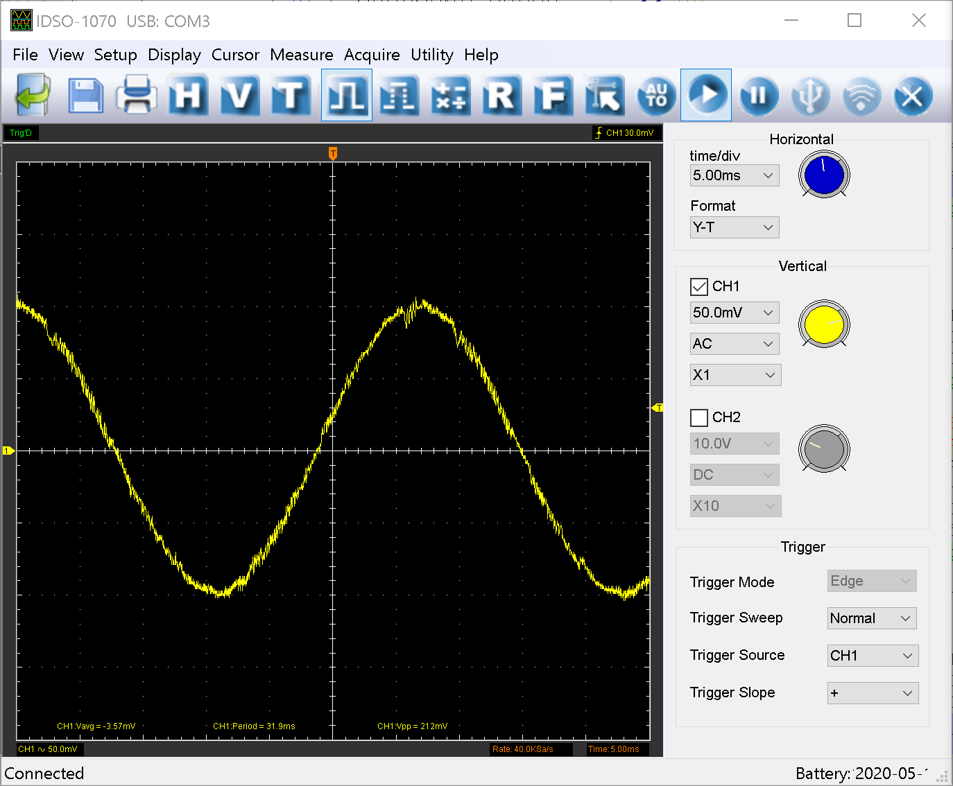
            This is how P6 performs (TBL = 1):

            B1_f300.png
            B1_f1800.png
            B1_f3600.png

            This also looks pretty good. Although it is a touch less smooth as before.

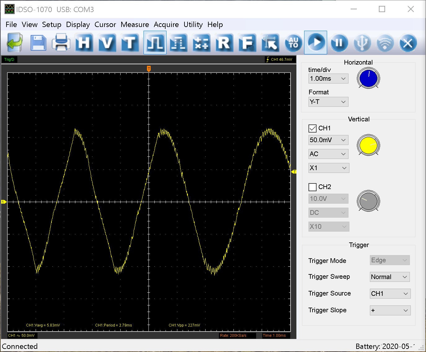
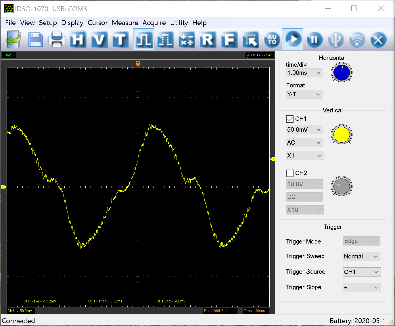
            Now to the black sheep in the flock, P5 (5mm/s for TBL 0,1 and 2):

            B0_f300.png
            B1_f300.png
            B2_f300.png

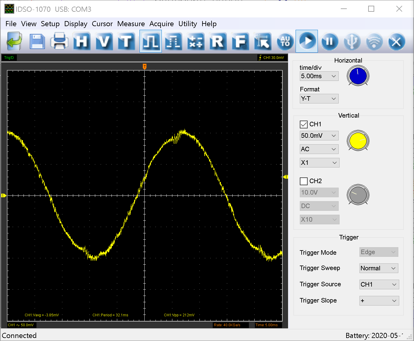
            I found that setting TBL to 1 seems to yield the best result, which is why I also used this setting for the other drivers. Taking a look at higher velocities, we can see that this driver definitely performs worse:

            B1_f1800.png
            B1_f3600.png

            Interestingly, P5 is the driver, which has this hole in the PCB to allow for a mechanical spacer.

            To do for me: Split up the two expansion boards I have and insert both P6 steppers into the P5+P6 sockets on the Maestro. I'll see if I can manage on the weekend (although I am not sure how to do this exactly. Don't want to break anything).

            To do for you guys: Please try to get your hands on the layout. This rough floorplan in the .pdf does not show any traces or ground planes.

            1 Reply Last reply Reply Quote 0
            • dc42undefined
              dc42 administrators
              last edited by

              Do you have identical stepper motors connected to P5 and P6?

              Duet WiFi hardware designer and firmware engineer
              Please do not ask me for Duet support via PM or email, use the forum
              http://www.escher3d.com, https://miscsolutions.wordpress.com

              1 Reply Last reply Reply Quote 0
              • Wurstkartonundefined
                Wurstkarton
                last edited by Wurstkarton

                I disconnected the cables from the motors and attached it to the same motor every time for the measurements.

                [Edit]: I'll try and set everything up on the weekend. I think I will be able to conclude if it is a problem with the expansion or with my setup.

                1 Reply Last reply Reply Quote 0
                • dc42undefined
                  dc42 administrators
                  last edited by

                  Do you find P5 noisier than P6 when driving the same motor at the same speed?

                  Duet WiFi hardware designer and firmware engineer
                  Please do not ask me for Duet support via PM or email, use the forum
                  http://www.escher3d.com, https://miscsolutions.wordpress.com

                  Wurstkartonundefined 1 Reply Last reply Reply Quote 0
                  • Wurstkartonundefined
                    Wurstkarton @dc42
                    last edited by

                    @dc42 yes. P6 is as quiet as the internal ones (more or less). P5 ist causing a lot of vibration and noise.

                    1 Reply Last reply Reply Quote 0
                    • dc42undefined
                      dc42 administrators
                      last edited by

                      You said you have two expansion boards. Is P5 noisy on both of them?

                      Duet WiFi hardware designer and firmware engineer
                      Please do not ask me for Duet support via PM or email, use the forum
                      http://www.escher3d.com, https://miscsolutions.wordpress.com

                      Wurstkartonundefined 1 Reply Last reply Reply Quote 0
                      • Wurstkartonundefined
                        Wurstkarton @dc42
                        last edited by Wurstkarton

                        @dc42 I just did the exercise and switched the expansion board. Same result.

                        I thought that it might be the cables. So I decided to switch those too. Also, I twisted the pairs, but that also did not have an impact.

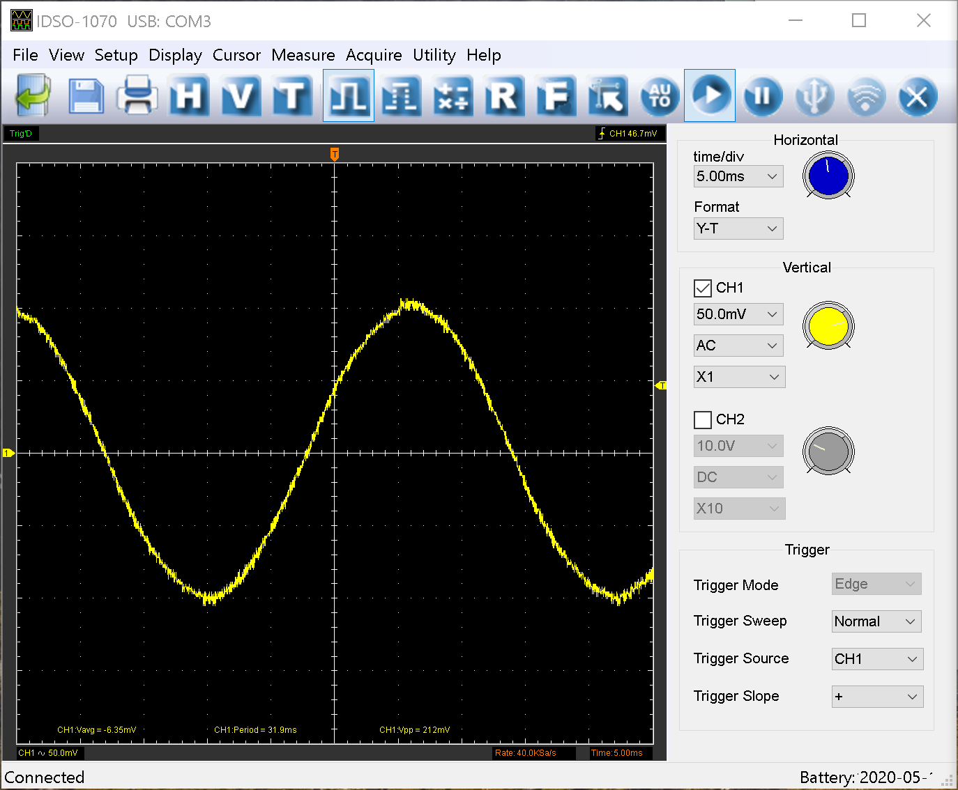
                        Some more insight I have found: only one of the two current paths is affected. Output 1 of P5. Output 2 is fine. Somehow the upper (well, upper depends on your point of view, but it is clear what I mean 😉 ) part of the sine wave gets a bit chopped of output 1.

                        Consequently, the two coils in the motor see a different current and hence are driven assymetrically. For me, it now looks like a bug (although it would be nice if someone else could try the same).

                        https://duet3d.dozuki.com/Wiki/Dual_Stepper_Driver_Expansion_Module

                        1 Reply Last reply Reply Quote 0
                        • Wurstkartonundefined
                          Wurstkarton
                          last edited by Wurstkarton

                          Okay. So I split up both of my expansions (one of which already had a groove and was easy, the other one was more work) and installed both "P6" to the Maestro.

                          Everything is running fine now! 🙂

                          Well, this concludes it for me. I have two leftover P5 - if someone is interested. 😏

                          1 Reply Last reply Reply Quote 1
                          • BotLawsonundefined
                            BotLawson
                            last edited by

                            Replacing the controller on a Chinese IDEX printer with a Duet 2 Maestro + Stepper Driver Expansion and I've run into this same problem. P5 is VERY noisy when it switches to SpreadCycle mode. Sounds almost like the stepper is stalled and you can feel the carriage vibrate while moving. (double checked the wiring, haven't crossed anything...) I'm using the same stepper motor on the P0 channel, and P0 is silent.

                            Anyone figured out what's wrong with the P5 stepper driver on the expansion? Does it need some components replaced? (wrong Capacitor or resistor somewhere?)

                            For now I've worked around it by setting the "V" parameter to 25 so it says in Stealth chop for most moves. It also got better when I swapped the X1 and X2 motors and wires. The motors are the same part number but, the X2 motor has longer wires.

                            M569 P5 S1 D3 V25                                 	; physical drive 5 goes forwards E2 (Very noisy!)
                            
                            Wurstkartonundefined 1 Reply Last reply Reply Quote 0
                            • Wurstkartonundefined
                              Wurstkarton @BotLawson
                              last edited by

                              @BotLawson I think there is a flaw with the design of the expansion. Even P6 produces slightly worse results than the internal steppers.

                              As for P5, there might be a way to fix it by comparing the layout of P5 with P6 and find the difference. Still missing this file though.

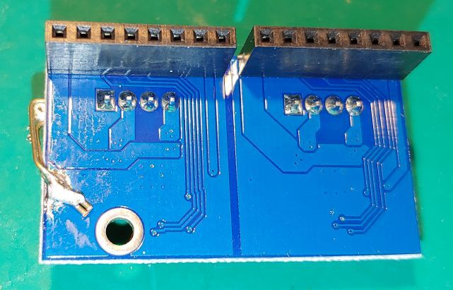
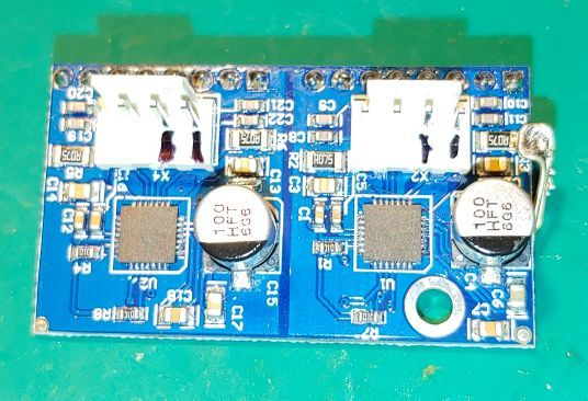
                              From looking at the PCB, there is not much to observe between the two...

                              1 Reply Last reply Reply Quote 0
                              • dc42undefined
                                dc42 administrators
                                last edited by

                                Do the passive components around the TMC2224 chip look identical on both parts of the boards that you have?

                                Duet WiFi hardware designer and firmware engineer
                                Please do not ask me for Duet support via PM or email, use the forum
                                http://www.escher3d.com, https://miscsolutions.wordpress.com

                                Wurstkartonundefined 1 Reply Last reply Reply Quote 0
                                • Wurstkartonundefined
                                  Wurstkarton @dc42
                                  last edited by

                                  @dc42 from what I could tell, yes. But that really does not mean much.

                                  The layout of output 1 (which is the output that generates the problem) looks a bit different, but I am not sure if this really would be a problem. Would be easier to see with the actual layout in a design tool.

                                  1 Reply Last reply Reply Quote 0
                                  • BotLawsonundefined
                                    BotLawson
                                    last edited by

                                    I do see some differences in the expansion board schematic. The 470pF ESD capacitors on the motor outputs have different voltage ratings. If the Duet 2 has NPO caps while the Expansion has Y5V (or even X7R) this might cause some noise as the higher capacitance capacitor dialectics are non-linear and piezoelectric while the NPO dialectic is nearly ideal.

                                    I'd also look closely at the grounding and parasitics of the current sense resistors on P5. That current wave-form sure looks like the current loop has started to go unstable. Might not need much series inductance to drive it over the edge. (the TMC2224 data sheet even warns about stray inductance on this circuit) Also check the supply decoupling for stray inductance or capacitor dialectic differences as these could can easily couple back into the loop.

                                    dc42undefined 1 Reply Last reply Reply Quote 0
                                    • dc42undefined
                                      dc42 administrators @BotLawson
                                      last edited by

                                      @BotLawson said in Duet Maesto Stepper Driver Expansion Schematic:

                                      I'd also look closely at the grounding and parasitics of the current sense resistors on P5.

                                      I suspect that's where the problem lies.

                                      Duet WiFi hardware designer and firmware engineer
                                      Please do not ask me for Duet support via PM or email, use the forum
                                      http://www.escher3d.com, https://miscsolutions.wordpress.com

                                      1 Reply Last reply Reply Quote 0
                                      • dc42undefined
                                        dc42 administrators
                                        last edited by

                                        I've managed to obtain the Gerber files for the expansion daughter board, and I think the difference between P5 and P6 can indeed be explained by layout differences - in particular, differences in the ground plane. Here is the top copper layer of the PCB.

                                        ce750f1d-8d92-485b-a903-fd6fddf448a0-image.png

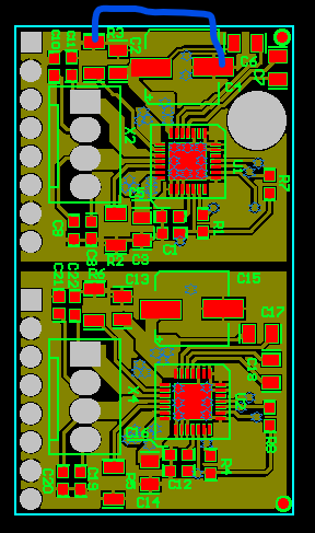
                                        The most significant difference I can see is that in the upper driver, the top (ground) end of sense resistor R3 has to go around a very long path to reach the decoupling capacitors and the ground pad of the chip. You could try adding a wire link as shown between the top end of R3 and either the ground end of the electrolytic capacitor C4 as shown (taking care not to short it against C6) or alternatively looping over the edge of the board to the bottom copper ground plane underneath the ground end of C4.

                                        Duet WiFi hardware designer and firmware engineer
                                        Please do not ask me for Duet support via PM or email, use the forum
                                        http://www.escher3d.com, https://miscsolutions.wordpress.com

                                        Wurstkartonundefined 1 Reply Last reply Reply Quote 0
                                        • Wurstkartonundefined
                                          Wurstkarton @dc42
                                          last edited by

                                          @dc42 Thank you for this analysis. At the moment, I do not have the need to try it out (as I have two P6). But I am sure that others may find it useful! 🙂

                                          1 Reply Last reply Reply Quote 0
                                          • BotLawsonundefined
                                            BotLawson
                                            last edited by

                                            ![I've been Printing PPE on my IDEX 3d printer recently. This ends up being a bit of torture test for the Meastro and expansion as I have all 7 steppers going constantly for 2 hours.

                                            The last couple of prints I had "P5 short circuit" errors that would trigger about 30min into a print after the controller and motors warmed up. But the prints would complete with almost no change to the motion of the extruder on P5. The extruder did stop for 5-10 seconds 2-3 times during the later prints, but re-started and completed the prints with no other issues.

                                            I assume that poor current loop stability can trigger a short circuit flag, so I went ahead and did a similar fix to what you suggested DC42. Only had a chance to do one test print with P5 in spread-cycle mode, but the short circuit errors are gone. I'll do more test prints in stealth-chop mode tonight to confirm.

                                            Attached are the front and back of my modified expansion.

                                            2020-05-30 11.13.20 small.jpg 2020-05-30 11.12.50 small.jpg

                                            Looking at the layout render, it looks like the culprit is the Vin trace to C6. It cuts off the direct path to ground and forces current from R3 to loop around the outside of the pcb. Personally, I'd put R3 and R2 between the TMC chip and stepper connector and give them 2-4 vias to the ground plane and the thermal die pad of the TMC. The motor phase connections can then sneak under or around the 805 resistor.

                                            Wurstkartonundefined 1 Reply Last reply Reply Quote 0
                                            • First post
                                              Last post
                                            Unless otherwise noted, all forum content is licensed under CC-BY-SA