Duet 3 - Motors only respond properly duing the home command
-
Please see my addition with the tool to select T1.
-
I went back in to the RRF Config tool and changed the Tool to "0" and tested again with the exact same results.
; Configuration file for Duet 3 (firmware version 3)
; executed by the firmware on start-up
;
; generated by RepRapFirmware Configuration Tool v3.1.1 on Sat May 30 2020 10:30:12 GMT-0700 (Pacific Daylight Time); General preferences
G90 ; send absolute coordinates...
M83 ; ...but relative extruder moves
M550 P"OLIVER3DPRINTER" ; set printer name
M665 R224.25 L573.75 B200 H600 ; Set delta radius, diagonal rod length, printable radius and homed height
M666 X0 Y0 Z0 ; put your endstop adjustments here, or let auto calibration find them; Network
M552 P0.0.0.0 S1 ; enable network and acquire dynamic address via DHCP
M586 P0 S1 ; enable HTTP
M586 P1 S0 ; disable FTP
M586 P2 S0 ; disable Telnet; Drives
M569 P0.0 S1 ; physical drive 0.0 goes forwards
M569 P0.1 S1 ; physical drive 0.1 goes forwards
M569 P0.2 S1 ; physical drive 0.2 goes forwards
M569 P0.3 S1 ; physical drive 0.3 goes forwards
M584 X0.0 Y0.1 Z0.2 E0.3 ; set drive mapping
M350 X256 Y256 Z256 I0 ; configure microstepping without interpolation
M350 E16 I1 ; configure microstepping with interpolation
M92 X10240.00 Y10240.00 Z10240.00 E837.20 ; set steps per mm
M566 X1200.00 Y1200.00 Z1200.00 E1200.00 ; set maximum instantaneous speed changes (mm/min)
M203 X18000.00 Y18000.00 Z18000.00 E1200.00 ; set maximum speeds (mm/min)
M201 X200.00 Y200.00 Z200.00 E1000.00 ; set accelerations (mm/s^2)
M906 X2000 Y2000 Z2000 E800 I50 ; set motor currents (mA) and motor idle factor in per cent
M84 S30 ; Set idle timeout; Axis Limits
M208 Z0 S1 ; set minimum Z; Endstops
M574 X2 S1 P"io1.in" ; configure active-high endstop for high end on X via pin io1.in
M574 Y2 S1 P"io4.in" ; configure active-high endstop for high end on Y via pin io4.in
M574 Z2 S1 P"io3.in" ; configure active-high endstop for high end on Z via pin io3.in; Z-Probe
M558 P0 H5 F120 T1200 ; disable Z probe but set dive height, probe speed and travel speed
M556 S50 X0 Y0 Z0 ; set orthogonal axis compensation parameters
M557 R200 S50 ; define mesh grid; Heaters
M308 S0 P"temp1" Y"pt1000" R2200 ; configure sensor 0 as PT1000 on pin temp1
M950 H0 C"out1" T0 ; create bed heater output on out1 and map it to sensor 0
M307 H0 B1 S1.00 ; enable bang-bang mode for the bed heater and set PWM limit
M140 H0 ; map heated bed to heater 0
M143 H0 S120 ; set temperature limit for heater 0 to 120C
M308 S1 P"temp2" Y"pt1000" R2200 ; configure sensor 1 as PT1000 on pin temp2
M950 H1 C"out2" T1 ; create nozzle heater output on out2 and map it to sensor 1
M307 H1 B0 S1.00 ; disable bang-bang mode for heater and set PWM limit; Fans
M950 F0 C"out3" Q500 ; create fan 0 on pin out3 and set its frequency
M106 P0 S0 H-1 ; set fan 0 value. Thermostatic control is turned off
M950 F1 C"out5" Q500 ; create fan 1 on pin out5 and set its frequency
M106 P1 S1 H1 T45 ; set fan 1 value. Thermostatic control is turned on; Tools
M563 P0 S"TITAM AQUA" D0 H1 F0 ; define tool 0
G10 P0 X0 Y0 Z0 ; set tool 0 axis offsets
G10 P0 R0 S0 ; set initial tool 0 active and standby temperatures to 0C; Custom settings
M575 P1 B57600 S1; Miscellaneous
M501 ; load saved parameters from non-volatile memory
M911 S10 R11 P"M913 X0 Y0 G91 M83 G1 Z3 E-5 F1000" ; set voltage thresholds and actions to run on power loss -
One more idea: is there a sys/config-override.g in the SD card?
-

-
I mean in the sys subdirectory.
-
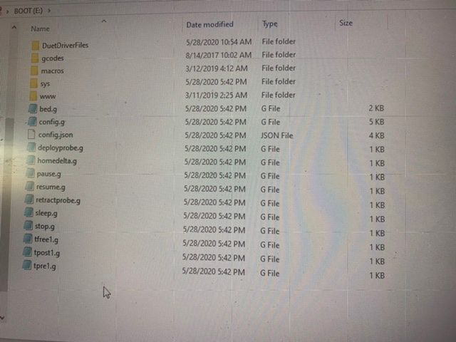
This is what I have on the SD card I had some problems during the initial setup because I replace some of the files on the SD card with some incorrect files but I thought I had fixed the problem buy downloading and installing all new files
-
An additional idea: are the endstops and steppers corresponding? (X stepper to X endstop etc.) because if Y is stopped by X endstop etc., this would explain why Y moves if you want to move X etc.
-
@JoergS5 Yes I have checked this all are connected to the appropriate motor.
-

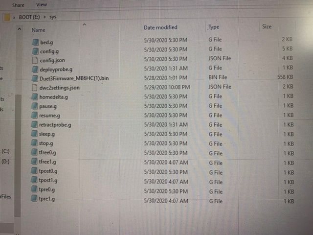
This is the contents of the sys folder on the SD card
-
Could you try the homing movements, but one axis after each other, whether this works:
G91
G1 H1 X815 F180 ;
G1 H1 Y815 F180 ;
G1 H1 Z815 F180 ; -
@Oliver3d are you sure because your steppers and endstops are a bit mixed:
M569 P0.0 S1 ; physical drive 0.0 goes forwards
M569 P0.1 S1 ; physical drive 0.1 goes forwards
M569 P0.2 S1 ; physical drive 0.2 goes forwards
M569 P0.3 S1 ; physical drive 0.3 goes forwards
M584 X0.0 Y0.1 Z0.2 E0.3 ; set drive mappingbut the endstops have different order:
M574 X2 S1 P"io1.in"
M574 Y2 S1 P"io4.in"
M574 Z2 S1 P"io3.in" -
@JoergS5 Yes this works correctly. Each axis homed independent from the others
-
At the moment this is my only idea: endstops and stepper don't match, so stepper positions are initialized wrong.
-
@JoergS5 I just tried homing all and manually activated the endstops individually to check the corresponding motor stopped and all worked as expected
-
Another idea: M114 will report the current XYZ positions. You could trying validating if positions are calculated correctly.
-
Another idea (I don't think this is the reason, because acceleration is low).
M203 X18000.00 Y18000.00 Z18000.00 E1200.00 ; set maximum speeds (mm/min)
set 18000 to 3000 e.g.
18000 are 300 mm/s and maybe too high.
And validate the current, 2000 could be too high if it's a Nema 17 (M906). Do your steppers get hot? -
@JoergS5 M114
X:0.000 Y:-0.000 Z:600.000 E:0.000 E0:0.0 Count 11551855 11551855 11551855 Machine 0.000 -0.000 600.000 Bed comp 0.000 -
And where is your hotend now? Your printer thinks your X and Y are bottom, Z top. Are the endstops same type (active high, low)
-
There is a specific section about endstop testing: https://duet3d.dozuki.com/Wiki/Connecting_endstop_switches#Section_Test_endstop_switches
-
@JoergS5 hotbed is centered on the bed at the maximum hight. So I believe X0 and Y0 are showing that it’s centered on the bed. And the Z600 is showing that it’s 600mm above the bed.