Duet 3 - Motors only respond properly duing the home command
-
-
This post is deleted! -
I have been struggling with this problem for the last two days, I’ve tried changing various different settings in the Duet setup configuration tool and always have the same result. Motors seem to work exactly as expected when the hoeing command is executed, but when I try to jog the print head in the z axis nothing happens, if I jog in the X axis the Z motor moves smoothly but only that motor, if I jog in the Y axis the X motor moves slowing and not smooth and the Y motor moves as it dose in the X axis jogging. I feel this must be a software problem because the homing cycle works perfectly.
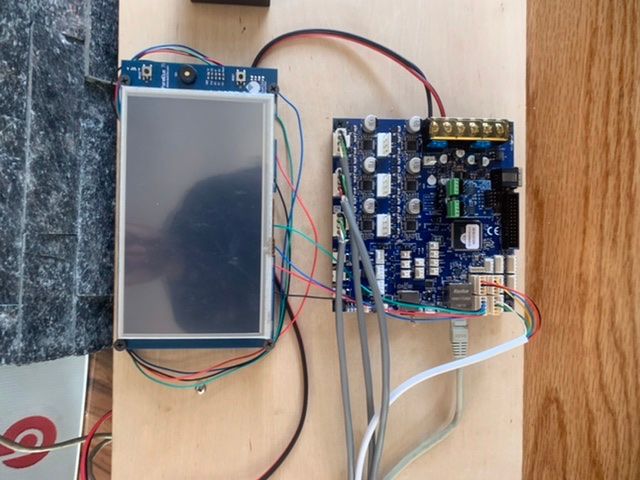
Ive tried all the steps I’ve done so far on the DWC and on the Paneldue that’s connected to the Duet board with exactly the same results. -
I have also tried top complete the delta configuration process but with no luck as I can’t get the head top jog down to the bed the DRO numbers are moving but the motors are not.
-
I am not sure whether your homing procedure is correct:
G91 ; relative positioning
;*** Slow homing has been configured. Change F180 to F1800 below when your configuration is working
G1 H1 X815 Y815 Z815 F180 ; move all towers to the high end stopping at the endstops (first pass)
G1 H2 X-5 Y-5 Z-5 F1800 ; go down a few mm
;*** Slow homing has been configured. Change F180 to F360 below when your configuration is working
G1 H1 X10 Y10 Z10 F180 ; move all towers up once more (second pass)means G1 movements with H1 parameter is individual motor mode and stopping at endstop, so it will stop when one of the axis is stopped.
In https://duet3d.dozuki.com/Wiki/ConfiguringRepRapFirmwareDeltaPrinter it is more like:
G91 ; use relative positioning
G1 S1 X300 Y300 Z300 F2500 ; move all carriages up 300mm, stopping at the endstops
G1 S2 X-5 Y-5 Z-5 ; move all towers down 5mm
G1 S1 X8 Y8 Z8 F500 ; move towers slowly up 8mm, stopping at the endstops
G1 S2 X-5 Y-5 Z-5 F10000 ; move carriages down 5mm
G90 ; back to absolute positioningSo S1 instead of H1 and S2 instead of H2.
The movement problems can then be due to one axis set correctly, but the other two not, so the printer thinks he is somewhere else as he is.
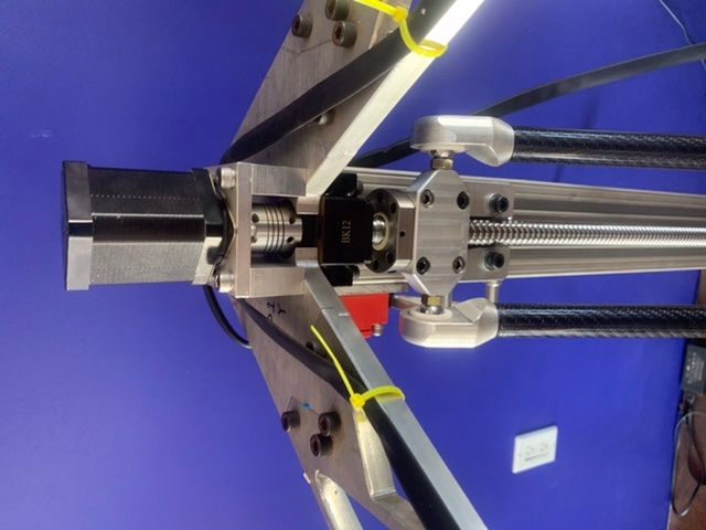
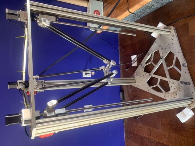
BTW nice printer with ball screws!!
-
I think I'm wrong, because thread https://forum.duet3d.com/topic/15279/duet-2-ethernet-3-01-rc5-fail-deltahome/2 used H1 and H2 and this worked.
My other idea at the moment is that you defined a tool 1, but no 0 tool. Maybe the movement tries to move a nonexisting tool 0. So T1 at the end of the config file maybe.
-
When I use the “S” commands the DWC tells me that this is an obsolete command and to replace the “S” with “H”.
I have lowered manually the 3 motors to completely different heights and the homing sequence raises all motors at the same speed until they each reach their appropriate endstops and then each motor waits for the remaining motors to catch up before doing the final bounce down and back to the stops.
I’m now going to try the homing sequence you have posted to see if this makes any difference
-
Please see my addition with the tool to select T1.
-
I went back in to the RRF Config tool and changed the Tool to "0" and tested again with the exact same results.
; Configuration file for Duet 3 (firmware version 3)
; executed by the firmware on start-up
;
; generated by RepRapFirmware Configuration Tool v3.1.1 on Sat May 30 2020 10:30:12 GMT-0700 (Pacific Daylight Time); General preferences
G90 ; send absolute coordinates...
M83 ; ...but relative extruder moves
M550 P"OLIVER3DPRINTER" ; set printer name
M665 R224.25 L573.75 B200 H600 ; Set delta radius, diagonal rod length, printable radius and homed height
M666 X0 Y0 Z0 ; put your endstop adjustments here, or let auto calibration find them; Network
M552 P0.0.0.0 S1 ; enable network and acquire dynamic address via DHCP
M586 P0 S1 ; enable HTTP
M586 P1 S0 ; disable FTP
M586 P2 S0 ; disable Telnet; Drives
M569 P0.0 S1 ; physical drive 0.0 goes forwards
M569 P0.1 S1 ; physical drive 0.1 goes forwards
M569 P0.2 S1 ; physical drive 0.2 goes forwards
M569 P0.3 S1 ; physical drive 0.3 goes forwards
M584 X0.0 Y0.1 Z0.2 E0.3 ; set drive mapping
M350 X256 Y256 Z256 I0 ; configure microstepping without interpolation
M350 E16 I1 ; configure microstepping with interpolation
M92 X10240.00 Y10240.00 Z10240.00 E837.20 ; set steps per mm
M566 X1200.00 Y1200.00 Z1200.00 E1200.00 ; set maximum instantaneous speed changes (mm/min)
M203 X18000.00 Y18000.00 Z18000.00 E1200.00 ; set maximum speeds (mm/min)
M201 X200.00 Y200.00 Z200.00 E1000.00 ; set accelerations (mm/s^2)
M906 X2000 Y2000 Z2000 E800 I50 ; set motor currents (mA) and motor idle factor in per cent
M84 S30 ; Set idle timeout; Axis Limits
M208 Z0 S1 ; set minimum Z; Endstops
M574 X2 S1 P"io1.in" ; configure active-high endstop for high end on X via pin io1.in
M574 Y2 S1 P"io4.in" ; configure active-high endstop for high end on Y via pin io4.in
M574 Z2 S1 P"io3.in" ; configure active-high endstop for high end on Z via pin io3.in; Z-Probe
M558 P0 H5 F120 T1200 ; disable Z probe but set dive height, probe speed and travel speed
M556 S50 X0 Y0 Z0 ; set orthogonal axis compensation parameters
M557 R200 S50 ; define mesh grid; Heaters
M308 S0 P"temp1" Y"pt1000" R2200 ; configure sensor 0 as PT1000 on pin temp1
M950 H0 C"out1" T0 ; create bed heater output on out1 and map it to sensor 0
M307 H0 B1 S1.00 ; enable bang-bang mode for the bed heater and set PWM limit
M140 H0 ; map heated bed to heater 0
M143 H0 S120 ; set temperature limit for heater 0 to 120C
M308 S1 P"temp2" Y"pt1000" R2200 ; configure sensor 1 as PT1000 on pin temp2
M950 H1 C"out2" T1 ; create nozzle heater output on out2 and map it to sensor 1
M307 H1 B0 S1.00 ; disable bang-bang mode for heater and set PWM limit; Fans
M950 F0 C"out3" Q500 ; create fan 0 on pin out3 and set its frequency
M106 P0 S0 H-1 ; set fan 0 value. Thermostatic control is turned off
M950 F1 C"out5" Q500 ; create fan 1 on pin out5 and set its frequency
M106 P1 S1 H1 T45 ; set fan 1 value. Thermostatic control is turned on; Tools
M563 P0 S"TITAM AQUA" D0 H1 F0 ; define tool 0
G10 P0 X0 Y0 Z0 ; set tool 0 axis offsets
G10 P0 R0 S0 ; set initial tool 0 active and standby temperatures to 0C; Custom settings
M575 P1 B57600 S1; Miscellaneous
M501 ; load saved parameters from non-volatile memory
M911 S10 R11 P"M913 X0 Y0 G91 M83 G1 Z3 E-5 F1000" ; set voltage thresholds and actions to run on power loss -
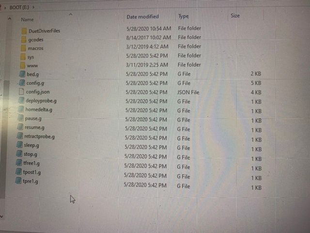
One more idea: is there a sys/config-override.g in the SD card?
-
-
I mean in the sys subdirectory.
-
This is what I have on the SD card I had some problems during the initial setup because I replace some of the files on the SD card with some incorrect files but I thought I had fixed the problem buy downloading and installing all new files
-
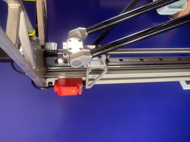
An additional idea: are the endstops and steppers corresponding? (X stepper to X endstop etc.) because if Y is stopped by X endstop etc., this would explain why Y moves if you want to move X etc.
-
@JoergS5 Yes I have checked this all are connected to the appropriate motor.
-
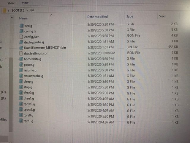
This is the contents of the sys folder on the SD card
-
Could you try the homing movements, but one axis after each other, whether this works:
G91
G1 H1 X815 F180 ;
G1 H1 Y815 F180 ;
G1 H1 Z815 F180 ; -
@Oliver3d are you sure because your steppers and endstops are a bit mixed:
M569 P0.0 S1 ; physical drive 0.0 goes forwards
M569 P0.1 S1 ; physical drive 0.1 goes forwards
M569 P0.2 S1 ; physical drive 0.2 goes forwards
M569 P0.3 S1 ; physical drive 0.3 goes forwards
M584 X0.0 Y0.1 Z0.2 E0.3 ; set drive mappingbut the endstops have different order:
M574 X2 S1 P"io1.in"
M574 Y2 S1 P"io4.in"
M574 Z2 S1 P"io3.in" -
@JoergS5 Yes this works correctly. Each axis homed independent from the others
-
At the moment this is my only idea: endstops and stepper don't match, so stepper positions are initialized wrong.
