• Tags
  • Documentation
  • Order
  • Register
  • Login
Duet3D Logo Duet3D
  • Tags
  • Documentation
  • Order
  • Register
  • Login

RRF 3 Z home not triggering.

Scheduled Pinned Locked Moved
Tuning and tweaking
6
91
4.2k
Loading More Posts
  • Oldest to Newest
  • Newest to Oldest
  • Most Votes
Reply
  • Reply as topic
Log in to reply
This topic has been deleted. Only users with topic management privileges can see it.
  • undefined
    joehsmash @fcwilt
    last edited by 3 Jun 2020, 05:51

    @fcwilt i agree with you there, so is there no way to use the Z axis endstops as a sudo probe? i know it wont be true leveling but its all i have for now seeing as my IR probe wont work.

    i read another post a while back where a guy got it to work, i sent him a message but hes long gone. granted this was on 2. something

    undefined 1 Reply Last reply 3 Jun 2020, 06:00 Reply Quote 0
    • undefined
      joehsmash @fcwilt
      last edited by 3 Jun 2020, 05:58

      @fcwilt ive located the post

      https://forum.duet3d.com/topic/4737/zprobe-robo3d-r1

      1 Reply Last reply Reply Quote 0
      • undefined
        fcwilt @joehsmash
        last edited by 3 Jun 2020, 06:00

        @joehsmash said in RRF 3 Z home not triggering.:

        @fcwilt i agree with you there, so is there no way to use the Z axis endstops as a sudo probe? i know it wont be true leveling but its all i have for now seeing as my IR probe wont work.

        While many things are possible in v3 firmware that are not in v2 (which is what I am still using) I cannot imagine how you could do that.

        Perhaps DC42 will jump in and address this question.

        Just out of curiosity do you have bed leveling thumbscrews or something like them for manually adjusting the bed?

        I built a printer not too long ago with three Z motors and a BLTouch Z probe to try automatic bed leveling. While it worked it was more complicated and noisy than my FT5 which used one Z motor and manual bed leveling and didn't work any better.

        I re-built it with one Z motor belted to two lead screws on opposite sides of the bed, much like the FT5, and a BLTouch Z probe.

        I'm much happier with that arrangement.

        Something to consider.

        Frederick

        Printers: a small Utilmaker style, a small CoreXY and a E3D MS/TC setup. Various hotends. Using Duet 3 hardware running 3.4.6

        undefined 1 Reply Last reply 3 Jun 2020, 06:05 Reply Quote 0
        • undefined
          joehsmash @fcwilt
          last edited by 3 Jun 2020, 06:05

          @fcwilt @dc42 has chimed in before to help.

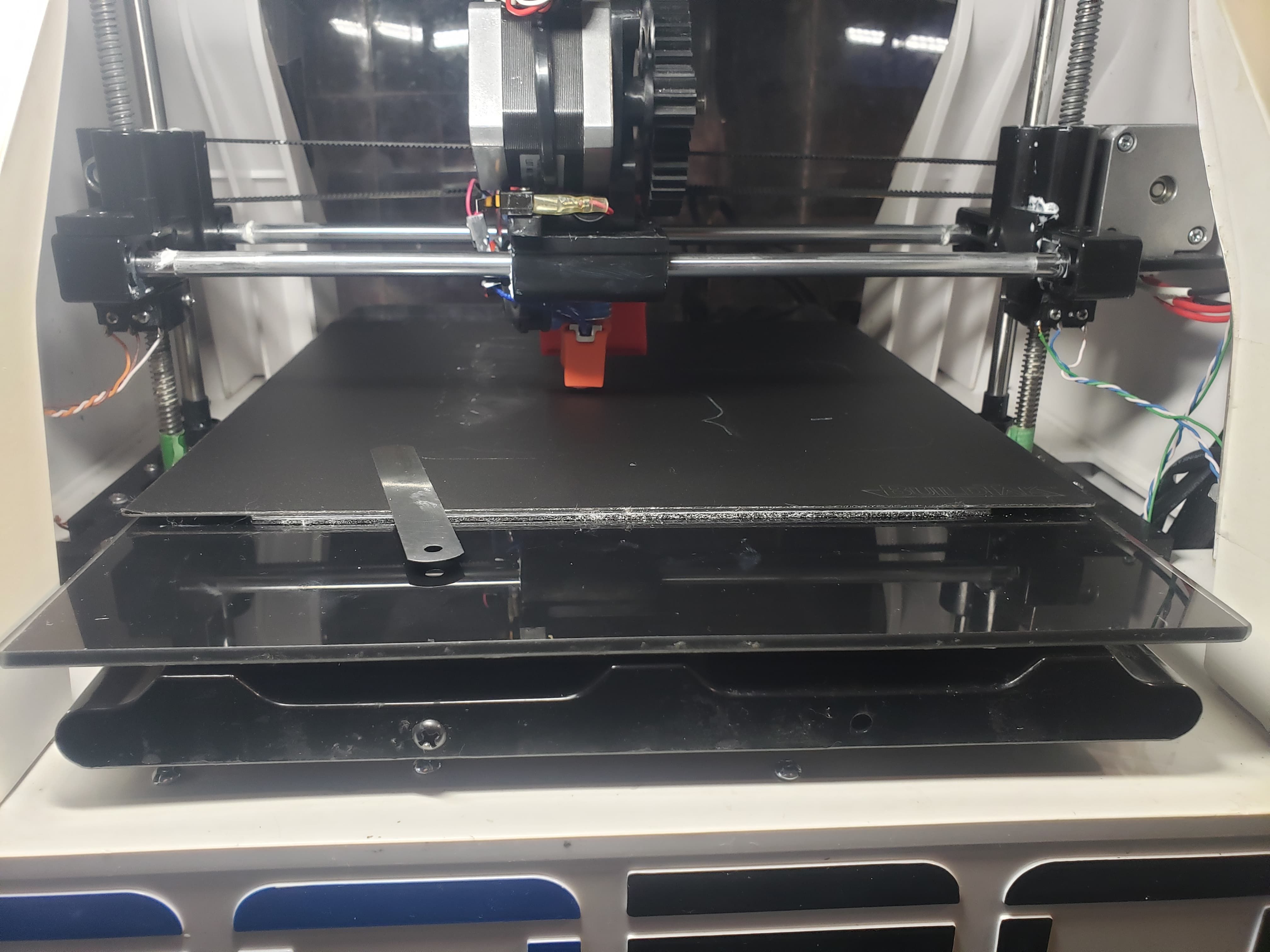
          i do not have levelling screws on my bed. its actually held to the y gantry with magnets that are epoxied to the bottom of the glass bed.

          one of the future upgrades i have planned is to re design the y gantry supports to allow me to delete the magnets and add in a screw type adjustment.

          but with that said, i have manually leveled and used metal shims that tto get all of the magnets to within 0.01 so the bed it self is level, just the zmotors arent and im not sure how to get the one driver for E0motor to come up or down.

          i also just ordered a BLtouch, how ever with the design of my xcarriage its going to be a challenge getting that set up. but again i will likely need to reprint the carriage to get it to work as i want.

          1 Reply Last reply Reply Quote 0
          • undefined
            jay_s_uk
            last edited by 3 Jun 2020, 06:10

            This applies to you
            https://forum.duet3d.com/topic/16766/offset-for-dual-y-endstop/3
            obviously you apply it to Z rather than Y. But you can adjust one of them (probably the one that reads 1.45) down by ~-0.65 so they are both at the same height.

            Owns various duet boards and is the main wiki maintainer for the Teamgloomy LPC/STM32 port of RRF. Assume I'm running whatever the latest beta/stable build is

            undefined 1 Reply Last reply 3 Jun 2020, 06:15 Reply Quote 0
            • undefined
              fcwilt
              last edited by 3 Jun 2020, 06:11

              For now can you couple the Z motors with a belt and use just one Z end stop switch?

              With that you could manually adjust the relationship of the two Z lead screws using one of the motor pulleys but one adjusted they would stay in sync.

              Frederick

              Printers: a small Utilmaker style, a small CoreXY and a E3D MS/TC setup. Various hotends. Using Duet 3 hardware running 3.4.6

              undefined 1 Reply Last reply 3 Jun 2020, 06:16 Reply Quote 0
              • undefined
                joehsmash @jay_s_uk
                last edited by 3 Jun 2020, 06:15

                @jay_s_uk thats great, i will most certainly try that out.

                all though im not sure why the second motor is losing distance.

                as i said before when i shoot the zheight up 50mm than back down the right one is off. so all though this would temporarily fix the problem (and i appreciate it) its not an ideal solution.

                but it is a solution to one of my problems none the less

                1 Reply Last reply Reply Quote 0
                • undefined
                  joehsmash @fcwilt
                  last edited by 3 Jun 2020, 06:16

                  @fcwilt said in RRF 3 Z home not triggering.:

                  adjusted they would stay in sync.

                  i most certainly could rewire my printer to have both of the z axis work off the same stepper, i though it was ideal in RRF3 to have each z as an individual motor, (its easier on the board as well as easier on the parts)

                  undefined 1 Reply Last reply 3 Jun 2020, 06:30 Reply Quote 0
                  • undefined
                    jay_s_uk
                    last edited by 3 Jun 2020, 06:22

                    @joehsmash It could be that your endstops aren't at exactly the same height. I know that doesn't explain the difference of 0.15 when backing off 50mm but it would explain the difference between 1.45mm and 0.95mm

                    Owns various duet boards and is the main wiki maintainer for the Teamgloomy LPC/STM32 port of RRF. Assume I'm running whatever the latest beta/stable build is

                    undefined 1 Reply Last reply 3 Jun 2020, 06:31 Reply Quote 0
                    • undefined
                      JoergS5 @joehsmash
                      last edited by JoergS5 6 Mar 2020, 06:31 3 Jun 2020, 06:30

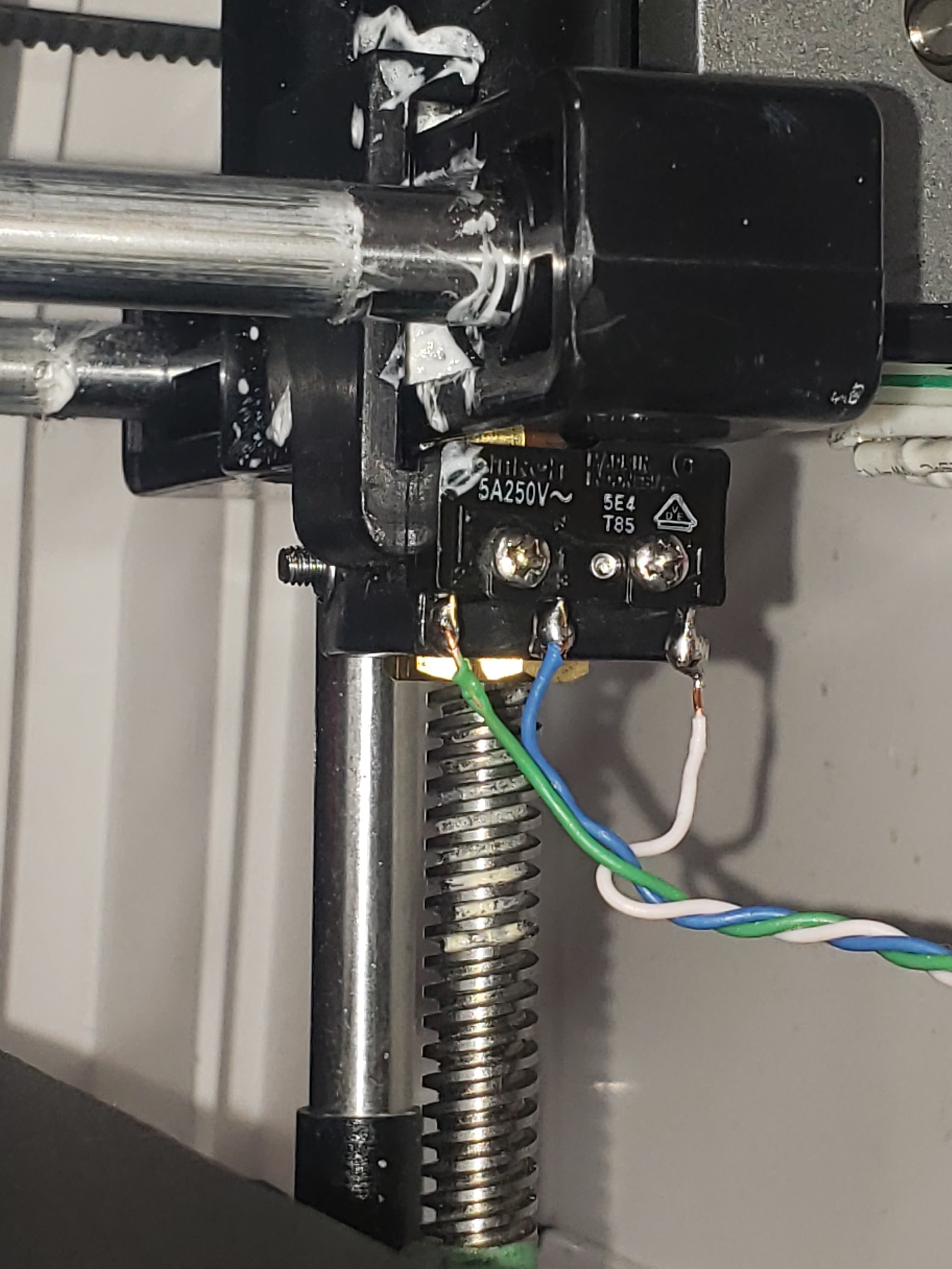
                      @joehsmash To use one Z stepper only is a good idea. Additionally you may have a mechanical problem with one side. It is easier to discuss this by seeing images from your construction, especially the connection between stepper and spindle/belt/whatever and how the bed/gantry is moved.

                      undefined 1 Reply Last reply 3 Jun 2020, 06:35 Reply Quote 0
                      • undefined
                        joehsmash @jay_s_uk
                        last edited by 3 Jun 2020, 06:31

                        @jay_s_uk this is a certain possibility. the way my gantry works is the lead screws are embeded into the x gantry, there is a clamp that holds the switches onto the underside of the gantry which is clamped onto the lead screws.

                        so to adjust them would put the entire weight of the gantry on one little screw which would move in the long run

                        1 Reply Last reply Reply Quote 0
                        • undefined
                          joehsmash @JoergS5
                          last edited by 3 Jun 2020, 06:35

                          @JoergS5

                          this is the construction of my printer

                          79006703_549962288998357_8917416021434826752_n.jpg 101446750_772706999931521_2509118373904777216_n.jpg 82092005_746864469454922_300562550108454912_n.jpg

                          1 Reply Last reply Reply Quote 0
                          • undefined
                            JoergS5
                            last edited by JoergS5 6 Mar 2020, 06:49 3 Jun 2020, 06:46

                            First I wonder why you have three cables at your endstops, because my are looking the same and two cables are sufficient: using left and right means closed when not active and they open when endstop is triggered.

                            I would expect some pressure between left and right, so if you change direction of one Z side, it will stuck at the trapezoid spindle. First test would be to let fixed the spindle and the linear guide on one side (let's say it is left), but loose the other (right) side a bit (trapezoid screw and linear guide) (like a fixed bearing and a loose bearing at CNC machines for installing ball bearings). So the right side can move a bit horizontally if necessary.

                            undefined 2 Replies Last reply 3 Jun 2020, 06:49 Reply Quote 0
                            • undefined
                              joehsmash @JoergS5
                              last edited by 3 Jun 2020, 06:49

                              @JoergS5 i just soldered on ones for the no, nc and common because i didnt want to have to dissasemble them to solder them if i ever needed to in the future, both of the NO contacts are disconnected underneith

                              undefined 1 Reply Last reply 3 Jun 2020, 06:50 Reply Quote 0
                              • undefined
                                JoergS5 @joehsmash
                                last edited by 3 Jun 2020, 06:50

                                @joehsmash ok I understand and it's ok of course.

                                1 Reply Last reply Reply Quote 0
                                • undefined
                                  joehsmash @JoergS5
                                  last edited by 3 Jun 2020, 06:53

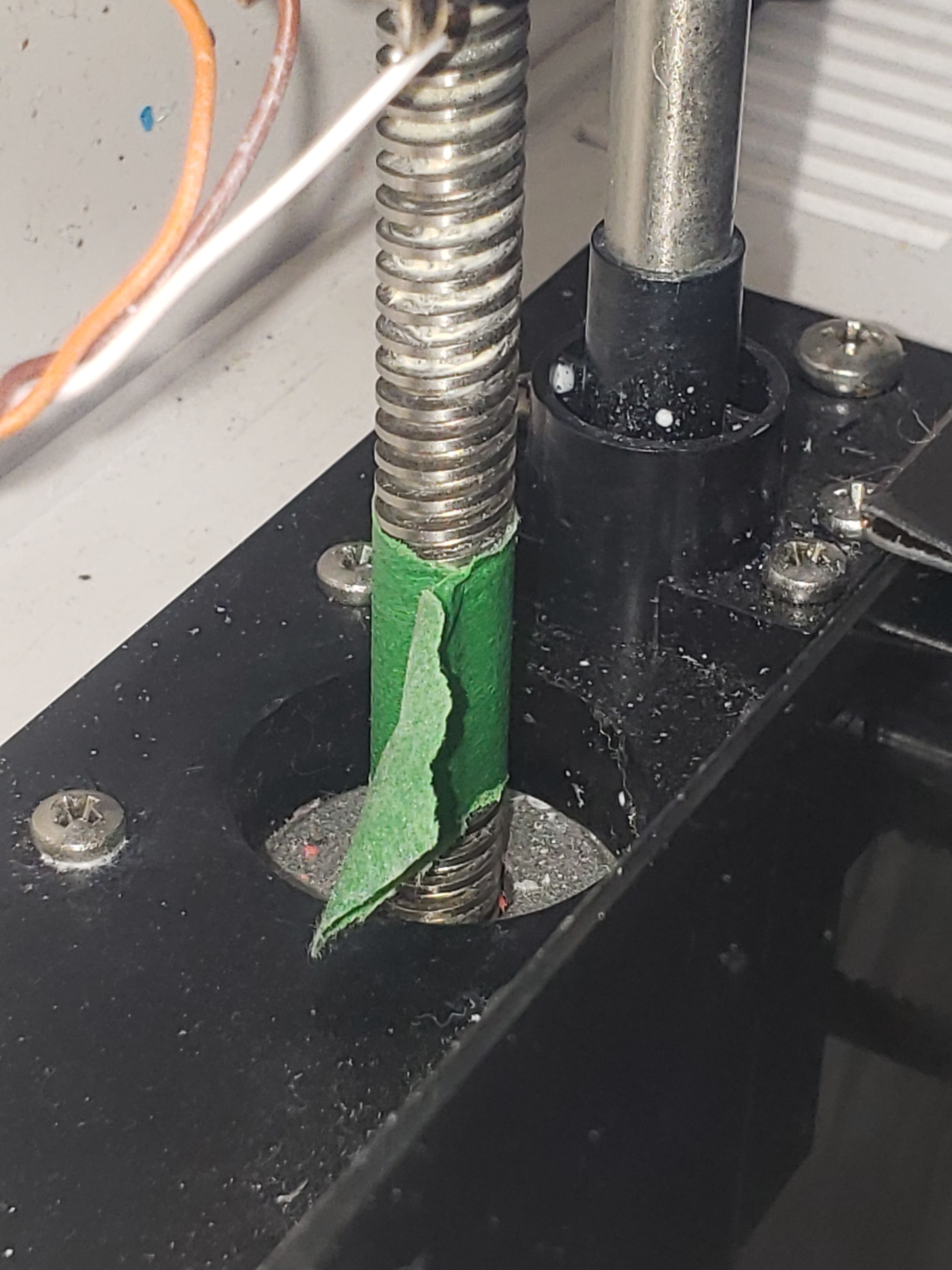
                                  @JoergS5 the construction of the lead screws are integrated into the stepper, so theres no adjustments that can be made.

                                  i can how ever manually adjust where the screw lays on the endstop clamp but for reasons i have posted before i wouldnt put all that pressure onto the one little tiny screw.

                                  1 Reply Last reply Reply Quote 0
                                  • undefined
                                    JoergS5
                                    last edited by 3 Jun 2020, 06:53

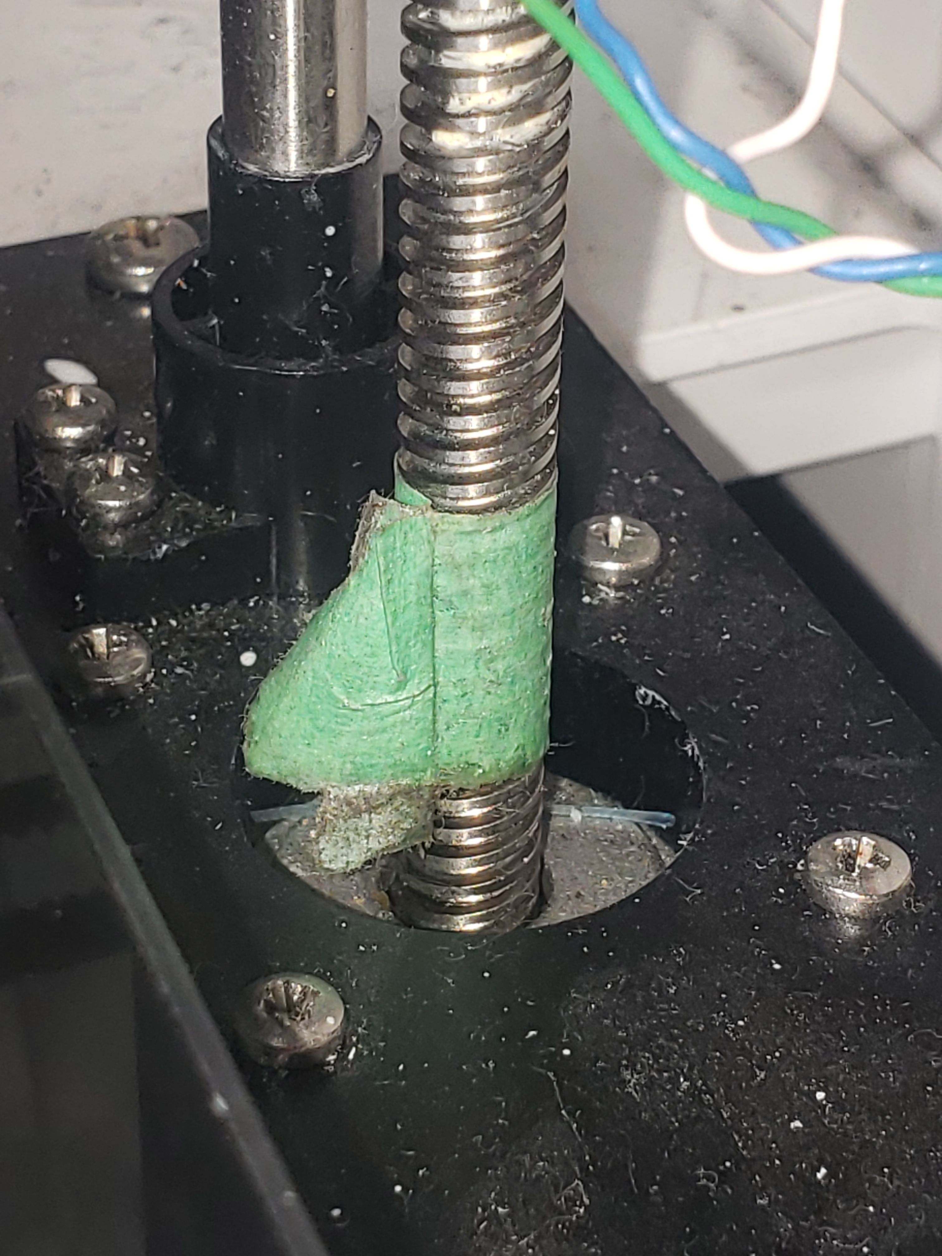
                                    And I cannot see exactly that this green connector is and how it is connected to the stepper, can you make a close picture of it please?

                                    undefined 1 Reply Last reply 3 Jun 2020, 06:54 Reply Quote 0
                                    • undefined
                                      joehsmash @JoergS5
                                      last edited by 3 Jun 2020, 06:54

                                      @JoergS5 the green your looking at it just tape, so i can visualize if each of the stepper is moving.

                                      i use it to verify if the mesh is working or not.

                                      1 Reply Last reply Reply Quote 0
                                      • undefined
                                        joehsmash
                                        last edited by 3 Jun 2020, 06:55

                                        20200603_005440.jpg
                                        20200603_005433.jpg

                                        1 Reply Last reply Reply Quote 0
                                        • undefined
                                          JoergS5
                                          last edited by JoergS5 6 Mar 2020, 06:57 3 Jun 2020, 06:57

                                          So the trapezoid spindle is directly inside the stepper? Or is there a coupler between?

                                          undefined 1 Reply Last reply 3 Jun 2020, 06:57 Reply Quote 0
                                          36 out of 91
                                          • First post
                                            36/91
                                            Last post
                                          Unless otherwise noted, all forum content is licensed under CC-BY-SA