Auto bed compensation working just not very well
-
; Configuration file for Duet 3 (firmware version 3)
; executed by the firmware on start-up
;
; generated by RepRapFirmware Configuration Tool v2.1.8 on Wed Apr 29 2020 12:52:20 GMT-0600 (Mountain Daylight Time)

; General preferences
G90                                          ; send absolute coordinates...
M83                                          ; ...but relative extruder moves
M550 P"Duet 3"                               ; set printer name

M669 K1                                      ; select CoreXY mode

; Configure panelDue

M575 P1 S1 B57600                            ; set to channel 1, panel due mode with checksum, baud 57600

; Drives
M569 P0.0 S1                                 ; physical drive 0.0 goes forwards
M569 P0.1 S1                                 ; physical drive 0.1 goes forwards
M569 P0.2 S0                                 ; physical drive 0.2 goes backwards
M569 P0.3 S0                                 ; physical drive 0.3 goes backwards

; Bed leveling
M671 X0.0:155.0:300.0 Y-8.0:242.0:-8.0       ; Define position of bed leveling screws

M584 X0.1 Y0.0 Z0.2 E0.3                     ; set drive mapping Y = drive 0 X = drive 1 Z = drive 2 Extruder drive 3

M350 X16 Y16 Z16 E16 I1                      ; configure microstepping with interpolation
M92 X200.00 Y200.00 Z1600.00 E420.00         ; set steps per mm
M566 X900.00 Y900.00 Z100.00 E120.00         ; set maximum instantaneous speed changes (mm/min)
M203 X6000.00 Y6000.00 Z600.00 E1200.00      ; set maximum speeds (mm/min)
M201 X500.00 Y500.00 Z20.00 E250.00          ; set accelerations (mm/s^2)
M906 X800 Y800 Z800 E1000 I30                ; set motor currents (mA) and motor idle factor in per cent
M84 S30                                      ; Set idle timeout

; Axis Limits
M208 X0 Y0 Z-3 S1                            ; set axis minima
M208 X300 Y310 Z300                          ; set axis maxima

; Endstops
M574 X1 S1 P"!io1.in"                        ; configure for low end, active-low endstop on X via pin io1.in
M574 Y1 S1 P"!io2.in"                        ; configure for low end, active-low endstop on Y via pin io2.in
M574 Z1 S1 P"!io3.in"                        ; configure for low end, active-low endstop on Z via pin io3.in

; Z-Probe
M950 S0 C"io4.out"                           ; create gpio servo 0 for BLTouch
M558 P9 C"io4.in" H2 F120 R.350 T6000        ; set Z probe to bltouch, set input to io 4 in, set dive height,set feed rate, set delay, set speeds
G31 P500 X-4 Y59 Z3.20                       ; set Z probe trigger Height, X and Y offset and trigger height
M557 X10:300 Y0:251 P3:3                     ; define mesh grid

; Heaters
M308 S0 P"temp0" Y"thermistor" T100000 B4138 ; configure sensor 0 as thermistor on pin temp0
M950 H0 C"out0" T0                           ; create bed heater output on out0 and map it to sensor 0
M143 H0 S110                                 ; set temperature limit for heater 0 to 110C
M307 H0 A236.8 C516.8 D3.0 V24.1 B0          ; disable bang-bang mode for the bed heater and set PWM limit
M140 H0                                      ; map heated bed to heater 0
M308 S1 P"temp1" Y"thermistor" T100000 B4138 ; configure sensor 1 as thermistor on pin temp1
M950 H1 C"out1" T1                           ; create nozzle heater output on out1 and map it to sensor 1
M143 H1 S260                                 ; set temperature limit for heater 1 to 260C
M307 H1 A445.5 C173.0 D5.5 V24.1 B0          ; disable bang-bang mode for hotend heater and set PWM limit

; Fans
M950 F0 C"out7" Q500                         ; create fan 0 on pin out7 and set its frequency
M106 P0 S0 H-1                               ; set fan 0 value. Thermostatic control is turned off
M950 F1 C"out8" Q500                         ; create fan 1 on pin out8 and set its frequency
M106 P1 S1 H1 T45                            ; set fan 1 value. Thermostatic control is turned on

; Tools
M563 P0 S"E3D-V6" D0 H1 F0                   ; define tool 0
G10 P0 X0 Y0 Z0                              ; set tool 0 axis offsets
G10 P0 R0 S0                                 ; set initial tool 0 active and standby temperatures to 0C

; Lights
M950 P1 C"out3"                             ; Create port on out 3 to power lights, 12v led strips are wired in series


; Custom settings are not defined

; Miscellaneous
T0                                           ; select first tool
My M557 looks wonky since the pei sheet size is 310X310, this was my attempt to compensate for no offset, I'm now aware of this flawed logic.
-
Alright, first steps are to make sure the M208 is correctly sized. 0,0 being the front left corner of the bed. The minima would be the far left and front positions where the endstops trigger and then from there you can move the head to the far right and back positions of travel to get the m208 maxima.
Then you can measure the probe offset with this: https://duet3d.dozuki.com/Wiki/Test_and_calibrate_the_Z_probe#Section_Measuring_Probe_X_Y_Offset
Then you can maximize the mesh grid by choosing the starting points for the minimum X Y that can actually be reached based on the offset. For example, If the probe is to the right of the nozzle by 20mm, it can't reach X10.
-
@Phaedrux said in Auto bed compensation working just not very well:
Alright, first steps are to make sure the M208 is correctly sized. 0,0 being the front left corner of the bed. The minima would be the far left and front positions where the endstops trigger and then from there you can move the head to the far right and back positions of travel to get the m208 maxima.
Then you can measure the probe offset with this: https://duet3d.dozuki.com/Wiki/Test_and_calibrate_the_Z_probe#Section_Measuring_Probe_X_Y_Offset
Then you can maximize the mesh grid by choosing the starting points for the minimum X Y that can actually be reached based on the offset. For example, If the probe is to the right of the nozzle by 20mm, it can't reach X10.
Ok, everything you have stated I understand. For reference my Z probe is 59mm behind and 4mm to the left of the nozzle. So for my offsets I have X-4 and Y59 as can be seen in the config.G file above.
This is what happens when I do a G29 with the above config.G. The nozzle heads for the front left corner 0,0 but stops short at 41mm in the Y plane which puts the probe at 100mm from the front edge of the pei plate, I'm losing 41mm of probe area. If I leave the Y offset at 0 then a G29 will probe with the nozzle going to Y0 putting the probe at 59mm. So why is 41mm sacrificed when there is an offset? Also I get the points not probed message, I don't get that message with 0 offset. This is the main reason I tried using 0 offsets. -
Can anyone tell me why I lose 41mm of probe(able) Y bed area when I have a 59mm Y offset? And what if anything can be done to correct it?
-
Please try
M557 X10:290 Y60:300 P3:3This should give you a 3x3 grid of the reachable area based on your values
M208 S1 X0 Y0
M208 S0 X300 Y310
G31 X-4 Y+59
If those values are correct this is what your reachable area looks like.
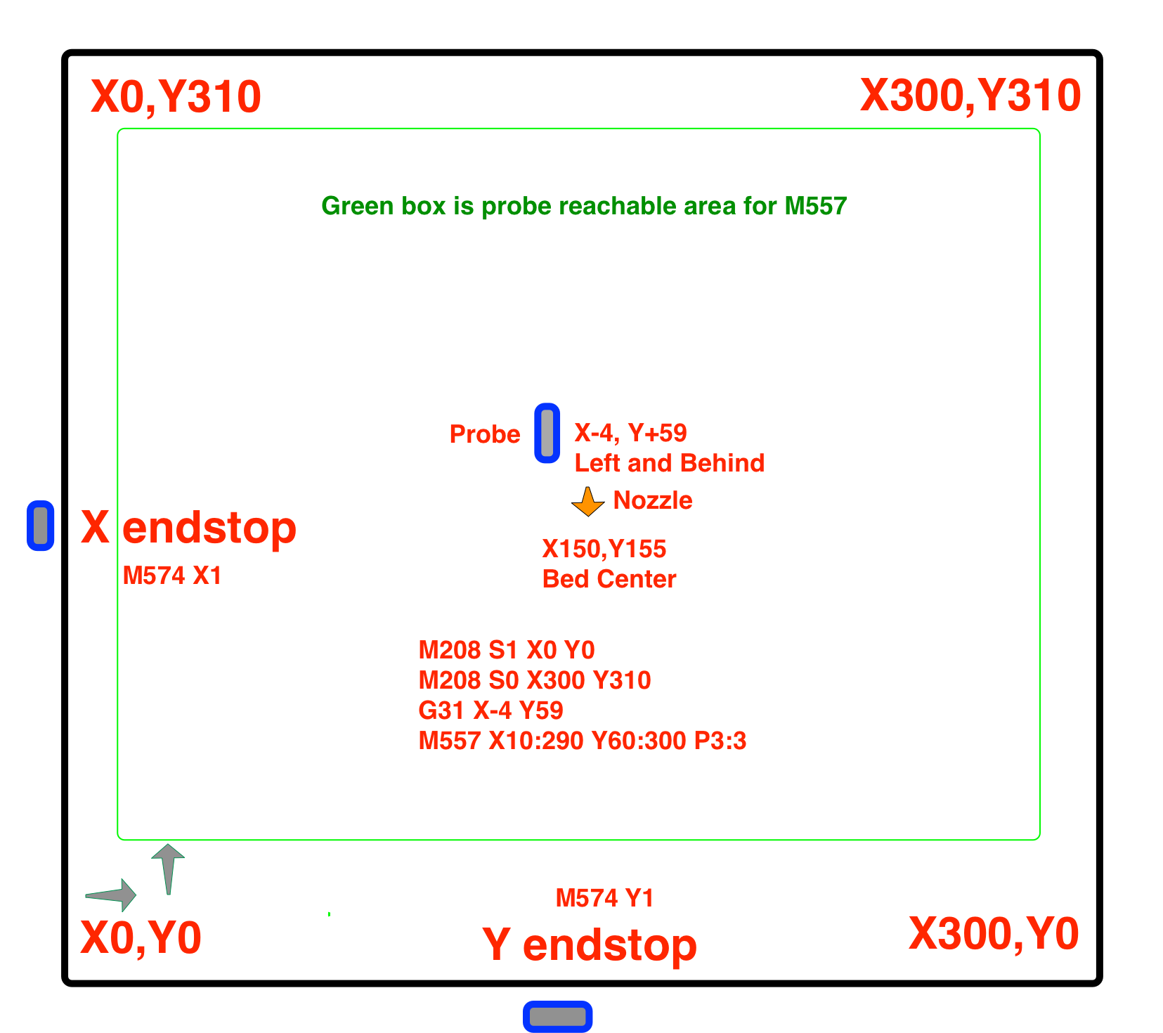
The green box isn't quite right, but you get the idea.
-
@Phaedrux Yes sir thank you for that. I've been playing with the offsets the better part of the day to try to understand The "if I do this it causes that". Getting my first layer down consistently over a large area is the only major thing I have left to tune on this printer.
Pretty well fried for the day will try your settings tomorrow. Very nice diagram btw.
-
@Phaedrux I used your M557 and G31 X-4 Y59 numbers and then a G32 which is .00 and .01 Then a G29. Then did a one layer test print with auto height adj active.

The print started in the lower left corner and is perfect. But right after the square of holes you can see an abrupt change. The nozzle is not as close to the bed. Bed adhesion is poor. As the print progresses from the lower left to the top right into the X it gets really bad getting a little better towards the print end. It is interesting (at least to me )that I got basically the same quality of print with and without the proper offsets. Here is height map.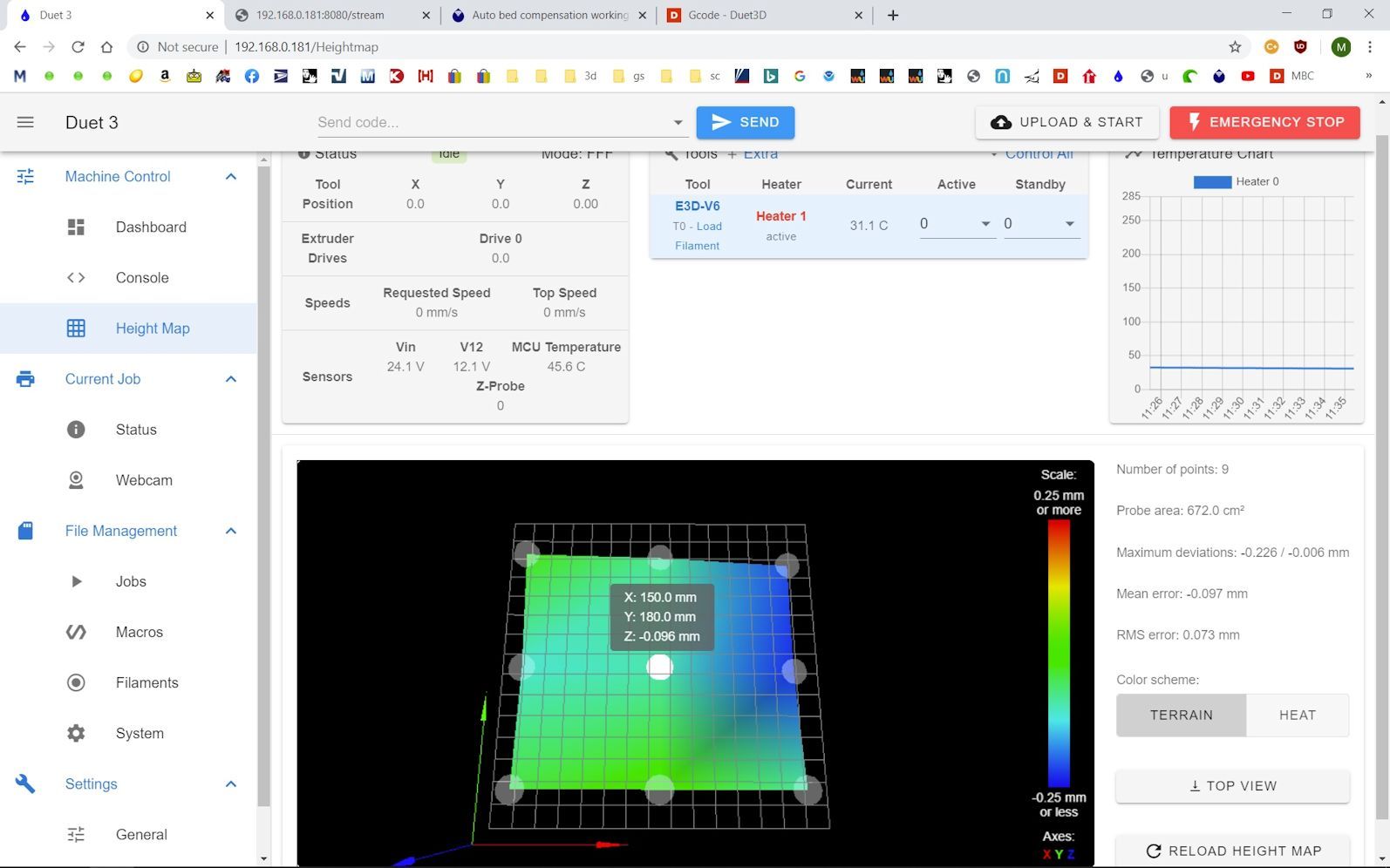
What I don't understand is why is Z -.096 for the center measurement? Since I'm using a BLtouch my homeall ends in a G30 at the center of the bed. Shouldn't the center measurement always be 0.00? I'm not aware of any further mechanical adjustment that should be done or redone to correct my first layer issues. My G32 is either perfect or near perfect.
All thoughts on this appreciated. -
Hi,
I always do a G30 right before probing with G29 and right before printing to try and compensate for any mechanical/temperature changes.
Also 9 points can give you a good overview of the bed but unless you know your bed is truly flat from edge to edge you will have to probe a lot more points for mesh comp to work well.
I probe by 300 x 300 bed using X and Y spacing of 20 mm.
Frederick
-
At this point I think it would be good if you could post your homing files and bed.g as well as your current config.g and your slicer start gcode so we can see the entire sequence of gcode events. Now that you have the grid correct there are some tweaks you can do to improve the results of the mesh.
-
; bed.g
; called to perform automatic bed compensation via G32
;
; generated by RepRapFirmware Configuration Tool v2.1.8 on Wed Apr 29 2020 12:52:20 GMT-0600 (Mountain Daylight Time)

; Remember to include probe offsets in X and Y coordinates
G28                          ; home
M401                         ; deploy Z probe
G30 P0 X11 Y55 Z-99999         ; probe left front adjusting screw
G30 P1 X296 Y55 Z-99999       ; probe right front adjusting screw
G30 P2 X152 Y305 Z-99999 S3  ; probe middle rear adjusting screw and report adjustments needed
M402                         ; retract probe
; homeall.g ; called to home all axes ; ; generated by RepRapFirmware Configuration Tool v2.1.8 on Wed Apr 29 2020 12:52:20 GMT-0600 (Mountain Daylight Time) G91 ; relative positioning G1 H2 Z7 F6000 ; lower bed 7mm to ensure probe is above the Z probe trigger height G1 H1 X-310 Y-310 F2600 ; move quickly to X or Y endstop and stop there (first pass) G1 H1 X-310 ; home X axis G1 H1 Y-310 ; home Y axis G1 X5 Y5 F6000 ; go back a few mm X and Y G1 H1 X-310 F360 ; move slowly to X axis endstop once more (second pass) G1 H1 Y-310 F360 ; then move slowly to Y axis endstop G90 ; absolute positioning G1 X157 Y99 F2000 ; Move probe over to the center of the bed G30 ; lower probe, stop when probe triggered and set Z to trigger height, home Z by probing the bed ; Uncomment the following lines to lift Z after probing ;G91 ; relative positioning ;G1 Z5 F100 ; lift Z relative to current position ;G90 ; absolute positioningAnd since the new bed is thicker than the oem bed I'm preheating for 10 minutes before I start a print.
I'm now printing the same print without height comp. Will post when finished. -
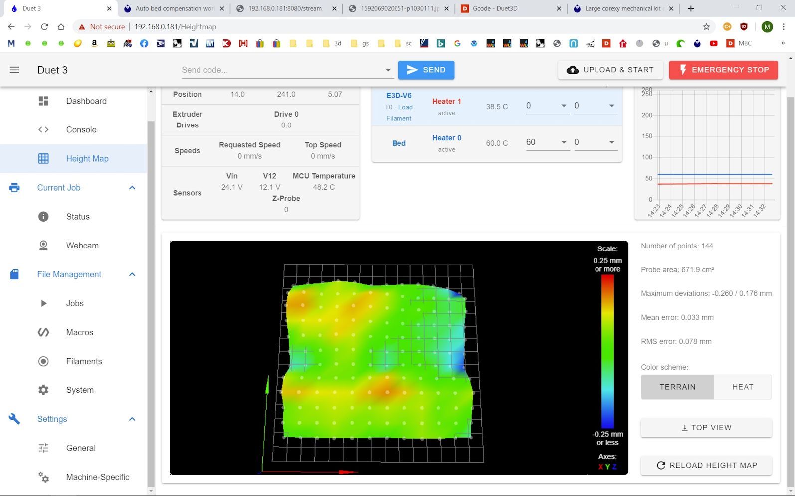
@fcwilt Heightmap done yesterday with many probe points. Made me wonder about the quality of plate I received. A print with this height map was about the same as above.
-
; bed.g

G28                          ; home all
M561      ; clear any bed transform

; first run
G30 P0 X11 Y55 Z-99999         ; probe left front adjusting screw
G30 P1 X296 Y55 Z-99999       ; probe right front adjusting screw
G30 P2 X152 Y305 Z-99999 S3  ; probe middle rear adjusting screw and report adjustments needed

; second run
G30 P0 X11 Y55 Z-99999         ; probe left front adjusting screw
G30 P1 X296 Y55 Z-99999       ; probe right front adjusting screw
G30 P2 X152 Y305 Z-99999 S3  ; probe middle rear adjusting screw and report adjustments needed

G90                     ; absolute positioning
G1 X157 Y99 F2000       ; Move probe over to the center of the bed
G30                     ; lower probe, stop when probe triggered and set Z to trigger height, home Z by probing the bed
; z probe in config.g M558 P9 C"io4.in" H2 F60 R0.5 T6000 A10 S0.003 ; set Z probe to bltouch, set input to io 4 in, set dive height,set feed rate, set delay, set speeds G31 P25 X-4 Y59 Z3.20 ; set Z probe trigger Height, X and Y offset and trigger height M557 X10:290 Y60:300 P12:12 ; define mesh gridMake these changes in config.g and bed.g, reboot, and then run G32 and then G29. That should home the printer, adjust lead screws twice, reestablish Z0, and then do a more detailed mesh grid. 3x3 lacks the detail needed and the interpolation between the sparse points is causing adjustment that isn't actually there. Your grid needs a higher resolution.
The changes to the BLTouch will make it probe more accurately, but it will take longer.
-
@Phaedrux Sounds good, thanks
Also sorry , did not see slicer start script,
G90 ; absolute positioning T0 ; select tool M109 S200 ; wait for hotend temp M190 S60 ; wait for bed temp G28 ; home all axes G29 S1 ; load height map G1 X130.0 Y15 Z0.0 F2000 ; move tool G1 X40.0 E10 F1000 ; prime nozzle G92 E0 ; reset extruder G1 E-.65 ; retract 1 mm -
Hi,
You can also try forcing the probe to average a fixed set of readings.
For example in M558 an A value of 5 and a S value of -1 the firmware will take 5 readings at each point then average them.
While averaging takes longer I think you would get a truer picture of your bed.
Frederick
-
That is what @Phaedrux did in the above files I believe.
-
Not quite. I have it probe up to 10 times or until it gets two consecutive consistent readings, but it won't average them. Averaging them would only be desirable if the probe results themselves were always shifting around and never consistent. We'd only want to go down that route it it was probing all 10 times and never getting two results the same. In such a case you'd get an error saying unable to get consistent probe result and it would halt the routine.
-
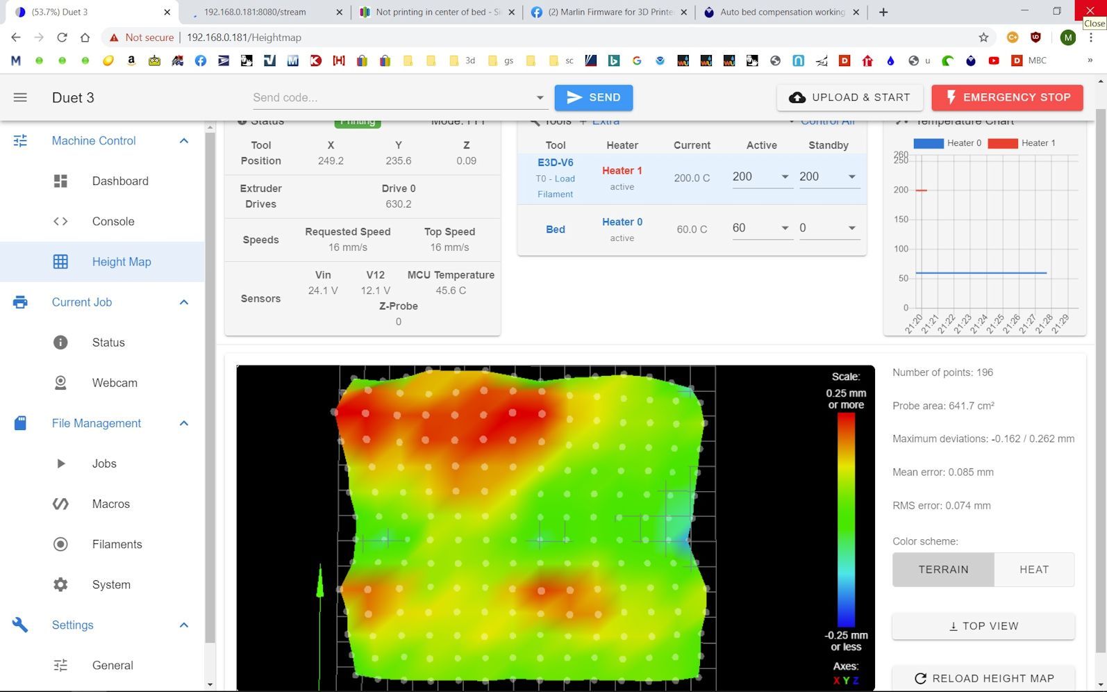
I've made the changes, copied and pasted. G32 ended up@ .01 and .01. Did G29, took a long time Here is the new print.

Height map
-
have you tuned the extruder? The second half of a good first layer is the right flow rate for the height from the bed.
-
Now that you've got a good height map generated you can use G29 S1 to load a saved heightmap instead of redoing it every time.
Print something like this to test the heightmap over the entire surface of the bed rather than a full print of a small section. Much faster this way and will give a better idea if the mesh compensation is working.
-
@Phaedrux I have confirmed the amount extruded by measuring 100mm of filament and then extruding 100mm. Comes out to within about a mm.