How to setup the Bigtreetech smart filament sensor?
-
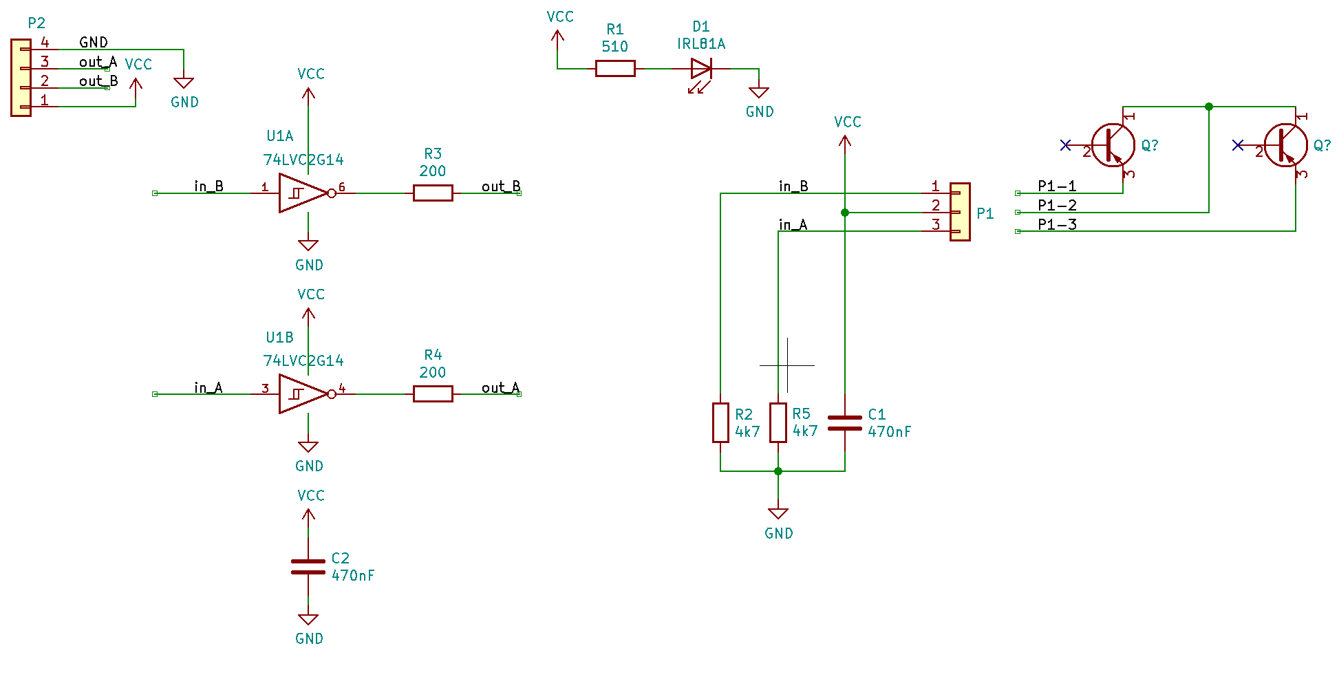
@arhi This is what I could find and its only confusing me more and more. If 4 &6 are supposed to be outputs one goes to what I thought was Vcc and the other to a pin that is not even connected to anything.
Based on the schematic I switched Vcc and Out around to test but then the IR led is turning on.
measure voltage between pins 2 and 5 (middle pins) on U1
2.55V
measure voltage across LED
1.113V
Measure voltage on U1 pins 1 and 3 (input)
measure voltage on U1 pins 4 and 6 (output) - check if they are inverted 1-3I am not really getting a consistent reading on both of them sometimes its around 1.1V, around 0.8V or nothing and 4&6 are usually inverted but not always
measure resistance U1 pins 4 and 6 to the signal pin on the connector
Pin6 - Signal = 1.3M ohm
Pin4 - Signal = 24.4 ohm -
@zapta said in How to setup the Bigtreetech smart filament sensor?:
@Infinitysnek said in How to setup the Bigtreetech smart filament sensor?:
with the resistor between Out and GND
I think arhi suggested a resistor between Out and Vin.
I tried it both ways, the first one was between Out and Vin the second between Out and GND
-
@Infinitysnek said in How to setup the Bigtreetech smart filament sensor?:
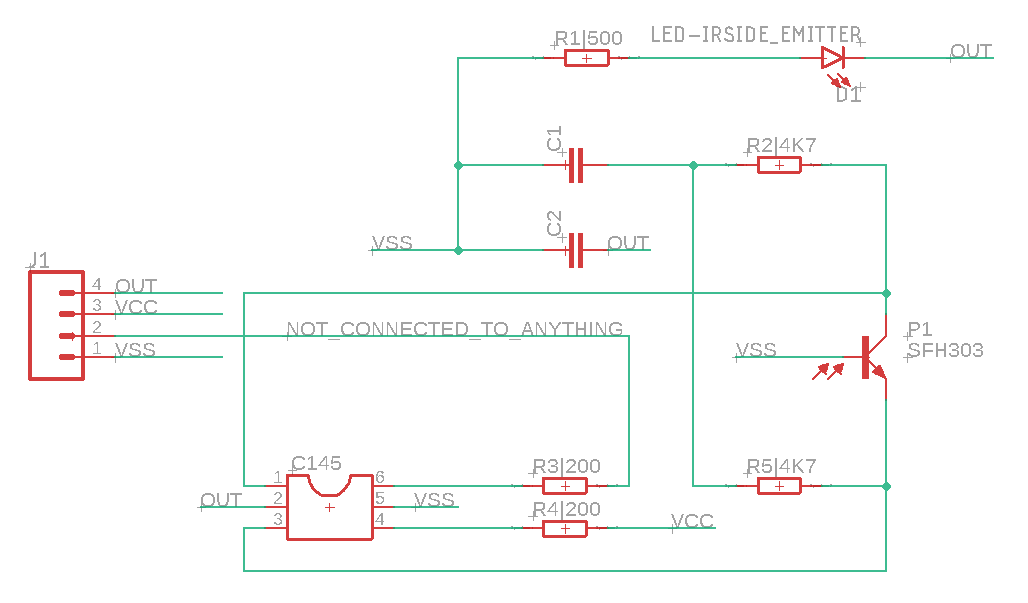
@arhi This is what I could find and its only confusing me more and more.
Looking at this schematic, I'd say the names on the J1 are all wrong

Fors start, the main thing to do is to get the IR led to power on.
In order to power the IR LED on you need Ground (Vss) to be on J1-4 and 5V (Vcc) on J1-1. Bringing 5V between pins 1 and 4 should get the LET to turn on as that will directly power the LED trough R1.
If that works, this will automatically properly power the C145 as U1-2 is Vss and U1-5 is Vcc and that correspond with 5V on J1-1 to J1-4.
In this case output of the U1 are pins J1-2 and J1-3 and are alternating from what I see so you should be able to use either as the signal to the duet's sensor input.
All this hoping that all the parts on the board are working ok, as by connecting them with wrong pinout you might kill the U1
Note that to test the outputs properly the whole thing needs to be closed or in the dark so that P1 only see the light from the IR diode and not ambient light.
-
@arhi I changed the pins around, this made the led turn on and got 3.3V over pin 2 - 5 so that's all good now. Measured the voltage over 1 & 3 while turning the wheel and that does seem to give a 1V pulse consistently but nothing happens overt 4 & 6. The IC is not getting hot so either something is going wrong or the IC is already dead i guess?
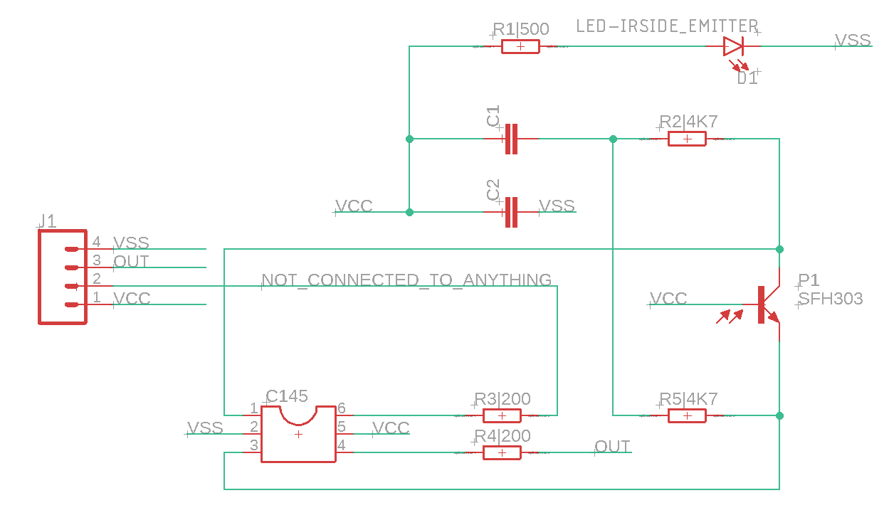
I updated the schematic to reflect the changes and I do have to say this makes more sense now
")
-
@Infinitysnek said in How to setup the Bigtreetech smart filament sensor?:
Measured the voltage over 1 & 3 while turning the wheel and that does seem to give a 1V pulse consistently but nothing happens overt 4 & 6.
The Vt+ when operating from 3V source per datasheet is 1.3-2.2V so 1V is not enough to trigger that schmitt. Check if will trigger better if you power the contraption from 5V.
Not sure if input on the duet is 5V tolerant (@dc42 should know) so if it works when powered from 5V you will probbly need a voltage divider on the output before feeding it to duet. But for now, just test it without any connection to duet.
To test the U1 on it's own you can bring Vcc to pin1 and expect 0V on the pin6 and also Vss to pin1 and expect 5V on pin6, just to be sure the U1 is not dead. Shorting U1-1 to Vcc or Vss should not damage anything.
BTW are you sure about schematic? The C1 seems weird, maybe they did it like this to just have a single pulse even if the hole is there for a while
-
@Infinitysnek said in How to setup the Bigtreetech smart filament sensor?:
have to say this makes more sense now
I have to say the schematic as a whole does not make too much sense to me.
Vcc directly on the base of the foto transistor will keep it always open ?!?! for e.g. maybe Vcc is in the collector? SFH303 is BCE footprint:
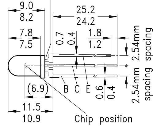
but from the pictures I see it's a square piece, not the round one so.. who knows what PRC made pos is that
Anyhow, assuming the schematic works 2 and 3 pins should have the pulses out if nothing is dead on that board.
-
@arhi Oh yes i could not find writing on the sensor so i just took something from the eagle library that roughly looked the same
-
yes probably the vcc is in the collector.. if that's npn at all ..
did you manage to test the U1 and output on J1-2 and J1-3 ?
-
@arhi said in How to setup the Bigtreetech smart filament sensor?:
To test the U1 on it's own you can bring Vcc to pin1 and expect 0V on the pin6 and also Vss to pin1 and expect 5V on pin6, just to be sure the U1 is not dead. Shorting U1-1 to Vcc or Vss should not damage anything.
I'm not exactly sure what you mean by this. Should i bridge Vcc or vss to U1-1 then measure over U1-6 and Vss?
With 5V I get a 1,7V pulse so that should be high enough however i'm getting a constant 1,3V on the output now
-
@Infinitysnek said in How to setup the Bigtreetech smart filament sensor?:
I'm not exactly sure what you mean by this. Should i bridge Vcc or vss to U1-1 then measure over U1-6 and Vss?
yes.
With 5V I get a 1,7V pulse so that should be high enough however i'm getting a constant 1,3V on the output now
I fear that U1 is dead. The schmitt output can only be 0 or Vcc (with a very little offset), the output of 1.3 on the 4 or 6 pin should only happen if you power it from 1.3V
-
@arhi Well thats too bad. The chips is fairly cheap at €2 for 20 so ill get some and replace the chip when it arrives in a month or so.
It is impossible for me to bridge the 2 pins and probe 2 others at the same time so Im going to assume its dead.Thank you for your help so far I really appreciate it

-
double check if those outputs go really directly to the connector trough 200R or maybe they have some other links that you missed but on the output pins really you should not see anything except 0/1 (Vss/Vcc).
Also, if you have any other schmitt inverter you can bodge it there.. should work..
-
@arhi I will check tomorrow. I don't have any schmitt inverters laying around but I did found another online: NC7WZ14P6X. Seems similar and should be here within a week.
-
@arhi I was going to replace the chip today until i found out its even smaller and doesn't fit
I ordered new ones but that will take a while to arrive...
-
if its pin-compatible you could try stretching and bending the legs to force it onto the bigger pad.
(apply liberal amounts of "carefulling" first)or solder thin wires from the pad to the leads. if current situation means huge delays I'd be inclined to try it.
edit: i've only had to use bigger chips on smaller pads, but having given it a second thought I'd flatten the legs to they come straight out the side of the chip to make up the missing length, angle them outwards to align with the pads, then just solder a wire between the pad on the board and lead of the chip that would otherwise be floating in air. once you got one down the rest should be simple-ish.
-
uh, I hate when it happens...
@omni will bring his one to me these days ('cause mine is not arriving for months now
) so I can do some real life testing here ... I finished the new "case" for my encoder last night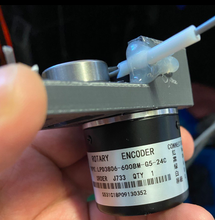
it's not a fancy package like the btree sensor but it does not restrict filament flow as much as btree one does and it's 600 impulses per rotation so ~8 impulses per mm instead of 1 impulse every 7mm
and these encoders are 5-6eur delivered so 3x cheaper than btree one anyhow I'm waiting for the tests you do after you replace the chip.
btw, one quick test you should be able to do during the weekend .. if you have hotair gun, heat it up a bit and just lift the pin1 and pin6 from the pcb so they don't touch any of the circuitry ... power the chip with 5V and measure output on the pin6 when you short the pin1 to ground and to 5V (should be easy to just solder a jumper wires so you can easily measure) just to be 100% sure that chip is dead ... or if you already desoldered it (I think you did), just solder the 4 wires (1,2,5,6) and try "in the air" ...
and I agree with @bearer few wires and that small one can fit, I did it more than once and still hate doing it but it's a fairly quick job if you have a steady hand and ok-ish vision
-
I have desoldered the chip already yes. I could try soldering on wires, hated doing that last time for a different project but it’s better than waiting a few weeks for new chips.
Does yours work with the duet? If this won’t play nice with the duet I could repurpose the housing for something like that
-
@Infinitysnek said in How to setup the Bigtreetech smart filament sensor?:
I could try soldering on wires, hated doing that last time
Useful hint, how I do it if I don't want to make a breakout board pcb - hot-glue
Put some hot-glue on a plate (wood, plastic, cardboard...) and put the chip on its back on that hot glue. This way the chip is held in place, the legs are up in the air much more accessible when the chip is "back up" compared to "back down". Use "magnet wire" (lacquered wire from a transformer or similar device). With some practice, you can even make whole circuits using that (dead bug) technique.
Does yours work with the duet?
Yes, I had it connected to duet for a while with old design I made, it was disabled but collecting data. Problem was that old design was not very good (not sure if new one is much better we'll see) so the filament got tangled few times and almost ruined the print so I redesigned it and will be adding it back on the duet. This encoders have Vcc, Vss, A and B outputs (AB is from encoder) and I'm using A to send signals to duet and it was working good. What I don't remember is what I used for Vcc :(, IIRC this thing has 7805 inside so can be powered from 6-12V. I have one DCDC hooked on my duet2 to produce 12V for various needs but no clue if that's how I was connecting it. I'll play with it on Sunday again so I'll make a separate post about how it works if anyone wants to use the same el-cheapo encoder from PRC (hoping someone will make a better housing for it
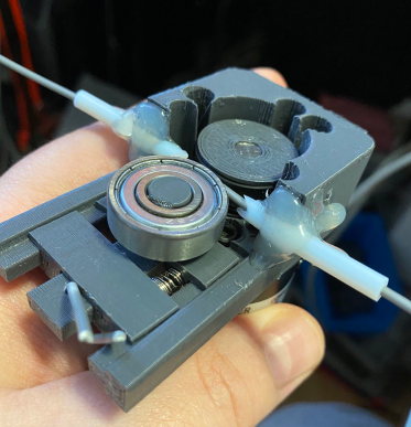
.. here if you can see from the images the 608 bearing slides on some rails, is pressed by the spring between that slider and external slider and externan slider is locked in place by the hole on the rail and piece of filament in that hole .... on the encoder's shaft I press fitted the printed wheel with concave edge and a wide rubber band wrapped around it to give it "grip" ... I glued the ptfe guide's 'cause during design I had no clue what the position of the wheels will be and after I did it was faster to just glue it in place than to change design and add more material with holes for those tubes -
Soldering wires wasn’t really a succes so I’ll wait for the other chip to arrive
-