Z Level
-
Hi *,
I'm sorry to bump that problem up again. That is still not solved and I want to spend some time now to solve that problem finally.
My newest findings are here:
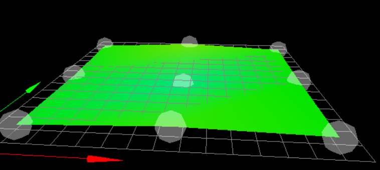
I guess that my M584 was wrong, I changed "Z2:9" to "Z9:2".I have a mesh which looks like that:
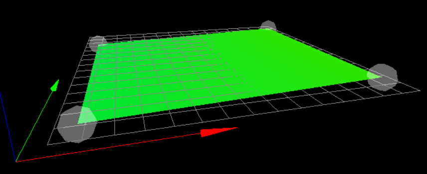
(4 points probed, min error -0.035, max error 0.025, mean -0.003, deviation 0.028)So it is clear that the distance on the right is a bit to high. I executed "G32" again, it came back with:
Leadscrew adjustments made: -0.230 -0.201, points used 2, (mean, deviation) before (-0.209, 0.016) after (-0.000, 0.000)G29 again:
4 points probed, min error -0.030, max error 0.017, mean -0.006, deviation 0.022G32:
Leadscrew adjustments made: -0.226 -0.206, points used 2, (mean, deviation) before (-0.211, 0.011) after (-0.000, 0.000)And guess what? The next G29 produced nearly the same result.
bed.g
G28 ; home
;M401 ; deploy Z probe (omit if using bltouch)
G30 P0 X20 Y155 Z-99999 ; probe near a leadscrew, half way along Y axis
G30 P1 X290 Y155 Z-99999 S2 ; probe near a leadscrew and calibrate 2 motors
;M402 ; retract probe (omit if using bltouch)
G1 X150     ; Back to the middle
The driver mapping:
M584 X0 Y1 Z9:2 E3                             ; Chriss - set drive mapping two Z motors connected to driver outputs E6(9) and Z(2)
M671 X-20:220 Y0:0 S2.5                        ; Chriss - leadscrews at left (connected to E6(9)) and right (connected to E2) of X axis (S=MaxCorrection)
The left (X0) leadscrew is connected to the expansion board and the right (Xmax) is connected the duet2.
I know that I have -0.023 on the left and 0.013 on the right. This is not a big "jump" and it may sound to you that I try to over optimize here and you are absolutely right with that. I simply want to understand what is going on here and whether that is the expected behavior or not.
")
Cheers, Chriss
-
M671 X-20:220 Y0:0 S2.5
That's saying your leadscrews are at -20,0 and 220,0, so bed is only 200mm wide in X, but your probing points are at X20 and X290. So I think your M671 should be:
M671 X-20:320 Y0:0 S2.5Ian
Bed-slinger - Mini5+ WiFi/1LC | RRP Fisher v1 - D2 WiFi | Polargraph - D2 WiFi | TronXY X5S - 6HC/Roto | CNC router - 6HC | Tractus3D T1250 - D2 Eth
-
Thnaks, that was a good idea.

M671 X-20:310 Y0:0 S2.5Because
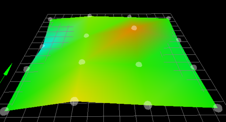
M208 X0:310 Y0:300The bed still looks like a battlefield of WWI:
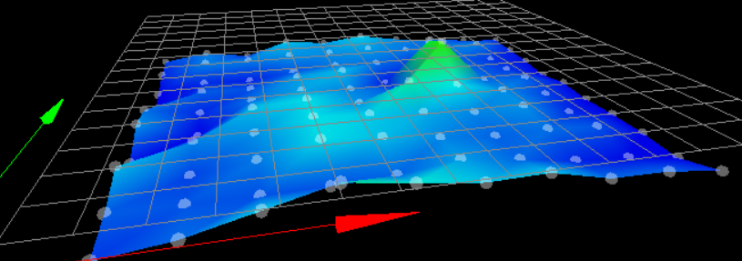
But this is a other story.
Cheers, Chriss
-
M671 X-20:310 Y0:0 S2.5
M208 X0:310 Y0:300Are your leadscrews actually at (-20,0) and (310,0)? Your M208 implies that the nozzle can get all the way to the leadscrew. The bed levelling will be most accurate if you give it accurate information.
What probe and bed surface are you using? If you're using an IR probe, and the bed is not uniform colour (eg has white writing on a black surface) this can throw off the IR reading. How is the probe mounted? There appears to be a 'barrel' distortion in the X axis. Post your probe config so we can check it.
Ian
Bed-slinger - Mini5+ WiFi/1LC | RRP Fisher v1 - D2 WiFi | Polargraph - D2 WiFi | TronXY X5S - 6HC/Roto | CNC router - 6HC | Tractus3D T1250 - D2 Eth
-
@droftarts said in Z Level:
Are your leadscrews actually at (-20,0) and (310,0)?
Well -20 is probably more accurate than the 310. But the bed is only 310 wide and the head can not travel much further. I extended it now to 320 as you mentioned. But at the end is the leveling nicely when I measure 4x4 points.
I'm not sure that I understand the documentation fully.
https://duet3d.dozuki.com/Wiki/Gcode#Section_M671_Define_positions_of_Z_leadscrews_or_bed_levelling_screws
And honestly, I'm not sure where the parameters do come from.
When I rephrase my config is one lead screw at "-20,0" and the other at "320,0" right?
Well, that is obviously wrong, as you mention but I did not get it.So I think that something like
-20,155 and 320,155 is more accurate... maybe 330 or 340 for the one at the right. Well I will play with that a bit more.Your M208 implies that the nozzle can get all the way to the leadscrew. The bed levelling will be most accurate if you give it accurate information.
I guess I have/had a blocker in my understanding here. Is that correct that I can define values outside the actual bed size in M671?
What probe and bed surface are you using? If you're using an IR probe, and the bed is not uniform colour (eg has white writing on a black surface) this can throw off the IR reading. How is the probe mounted? There appears to be a 'barrel' distortion in the X axis. Post your probe config so we can check it.
Wow.... yes, we check that. But I have a recently talked with Phaedrux some days ago already about that in this thread: https://forum.duet3d.com/topic/17093/weird-headmap-since-ir-probe
In short:
IR probe, magnetic PEI sheet at the moment (similar behavior with fr4 and pertinax). I have two more probes hanging around for my corexy build. I exchanged the one at the CR10 for testing and both produce the same result. I tested with plain paper, that was not much better.I guess that that is all I need for the probe:
M558 P1 C"zprobe.in" H5 F120 T6000
G31 P500 X-26.0 Y-9.0 Z2.25
M557 X10:270 Y40:270 P10:10
Mechanically:

Cheers, Chriss
-
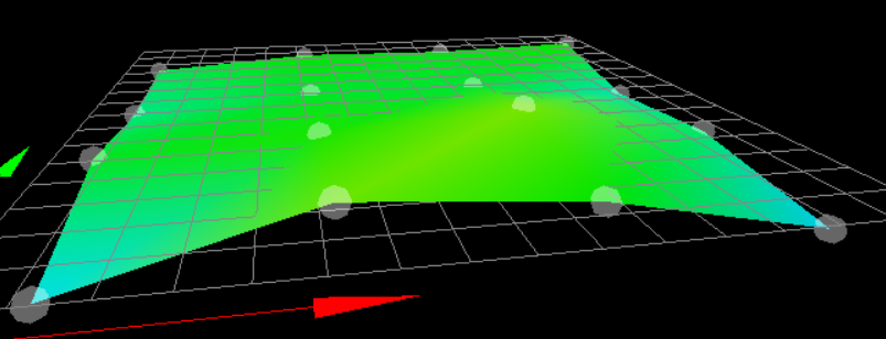
Update from the z-level cellar:
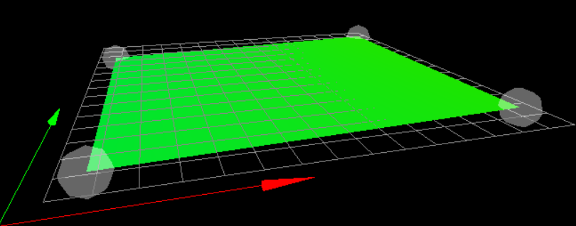
M671 X-20:330 Y155:155 S5.5That looks vary nice now:
On Ymin = left -0.003 right: -0.003
On Ymax= left 0.020 right: 0.025This is far better than expected
-
Wow....
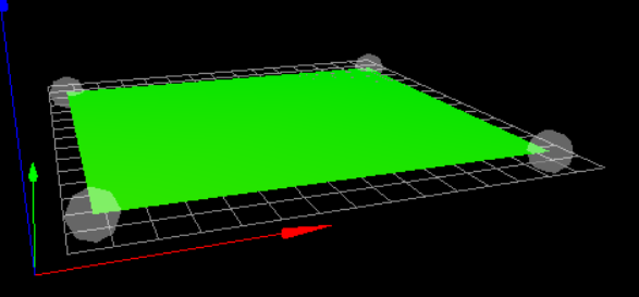
3x3:
4:4:

-
I turned the bet 180°:
Strange... strange...