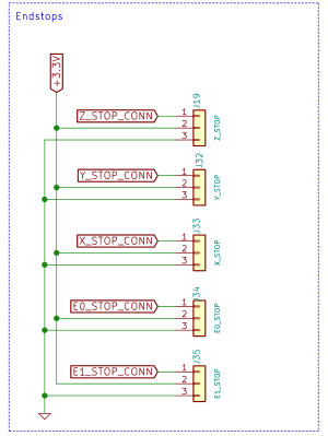
Endstop LED lighting, but DWC does not show them triggered
-
So I probed around a bit and for some reason my voltage divider setup is only bringing the voltage down to 1.2v instead of 0v.
Probably enough to trigger the LEDs but not the circuit.
I'll fix this tomorrow and report back.
-
Maybe draw us a picture, lots of seemingly contradicting bits in the posts here? Or refer to https://duet3d.dozuki.com/Wiki/Connecting_a_Z_probe#Section_PNP_output_normally_open_inductive_or_capacitive_sensor the wiring is relevant for endstops as well as probes.
-
So I traced the issue to the fact that all my endstops seem to have their pull-up resistors enabled, even though I never specified the pull-up flag.
(I'm seeing this on all the endstop input pins)Any thoughts on the matter would be appreciated as I try to hunt down this issue....
-
@Leav said in Endstop LED lighting, but DWC does not show them triggered:
So I traced the issue to the fact that all my endstops seem to have their pull-up resistors enabled
they're physical resistors on the board.
you need to add pull down to counteract ref post above.
-
@bearer said in Endstop LED lighting, but DWC does not show them triggered:
they're physical resistors on the board.
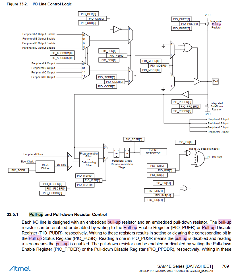
Are you sure? I was looking at the schematic and couldn't find any pull-ups and the Atmel datasheet mentions software defined pull-ups and pull-downs:
-
Ok this section was hiding to the side! oops!
-
if your endstops are PNP then please try the wiring described in https://duet3d.dozuki.com/Wiki/Connecting_a_Z_probe#Section_PNP_output_normally_open_inductive_or_capacitive_sensor
-
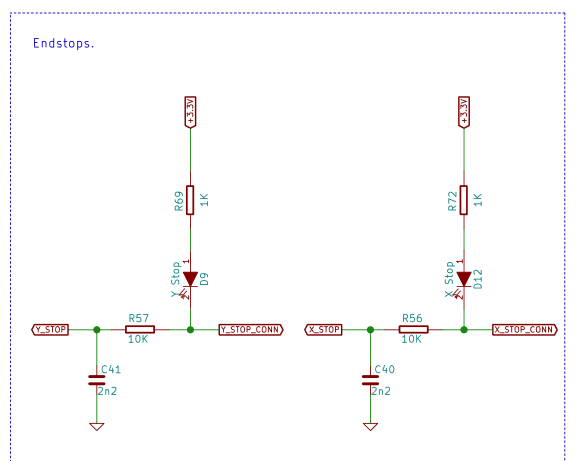
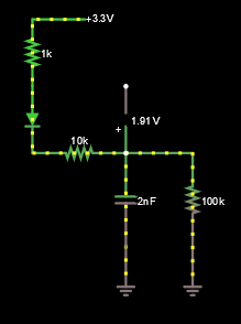
I don't see how that would solve it... would still result in ~1.5v on the input:
(This model is missing the internal pulldown resistor in the atmel, I think. But I don't know it's value)
edit: Looks like the internal pull-down on the Atmel is 100K nominal:
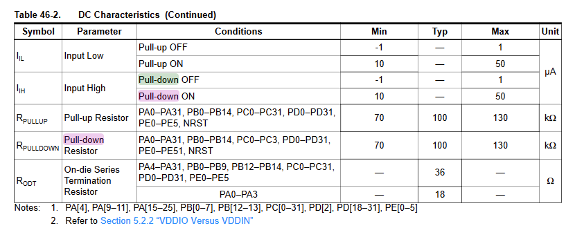
And obviously I'm in over my head here since I don't see how the duet design works with that "1k pullup" and the LED... Falstad Circuit Simulator says the voltage on the input would not be pulled down effectively...
-
Your drawing isn't correct for a PNP sensor, it would be a swtich to 24v not to ground.
(edit: if your sensor switches to ground then its a NPN sensor and you can connect the output directly to the duet input and use the internal pull up, no external resistors required)
-
First, I would like to say thanks for supporting and trying to help - very much appreciated!
Second, it's an NPN sensor:
I suppose I could try the diode design proposed here, but not sure I have any diodes. Is there anyway to make it work with resistors?
Also not sure I understand why it would work, but not surprising since I don't understand any of the circuit.... (how does the LED not pull up the voltage to ~1.5v? is the falstad simulation wrong? did I draw the diagram wrong?)
-
If your device has an open collector output that connects to ground when active you should be able to treat it as a switch.
Have you verified that there is a voltage on the output when simply powered up and the output is not connected to anything?
Frederick
-
@fcwilt Hi, Yes I can confirm that when the sensor is disconnected, I get 24v when untriggered and 0v when triggered.
Do you mean just connect it as is to the board? won't that dump ~24v into the endstop circuit? I seem to remember reading that the LEDs can only handle ~8v....
-
No don't connect to the board.
I just wanted to know if the device had an pure open collector output (no pull-up resistor) - meaning it would show no voltage with the output disconnected.
What you can do to limit the voltage to the Duet is to connect 4 diodes (example 1N4148) in series, with the anode of the first one connected to the Duet input and the cathode of the last one connected to the Duet ground. This would limit the voltage at the input to roughly 2.8 volts but should be high enough to not activate the Duet input.
Then you would connect a 1K resistor from the output of your device to the Duet input. This resistor would limit the current to roughly 24 mA and protect the diodes but should be small enough in value to activate the Duet input.
The diode listed is rated to 200 mA so you could use, say, a 512 resistor if the 1K does not activate the Duet input.
Frederick
Printers: a small Utilmaker style, a small CoreXY and a E3D MS/TC setup. Various hotends. Using Duet 3 hardware running 3.4.6
-
@Leav said in Endstop LED lighting, but DWC does not show them triggered:
Second, it's an NPN sensor:
you did start your thread saying it was a PNP sensor..
i'd perhaps suggest putting up the whole model number so you can get some help checking if it does have pull ups or have been damaged. Built in pull up on a NPN sensor is both uncommon and defeats the benefit of interfacing between different voltages.
-
@bearer said in Endstop LED lighting, but DWC does not show them triggered:
you did start your thread saying it was a PNP sensor..
Yup, forgot about that... to save face I can say I wasn't sure and added a question mark, but I could have just checked. Apologies.
@fcwilt said in Endstop LED lighting, but DWC does not show them triggered:
What you can do to limit the voltage to the Duet is to connect 4 diodes
That sounds... complicated, and I'm not sure I have any diodes. I think I'll try out alternative solutions first. might be time to just swap out to opto-endstops I have laying around somewhere.... hopefully they are 3.3v compatible...
@bearer said in Endstop LED lighting, but DWC does not show them triggered:
Built in pull up on a NPN sensor is both uncommon and defeats the benefit of interfacing between different voltages.
Thanks you for mentioning this! i'm not an EE but the pull up in that sensor did give me lots of headaches! would be so much simple if it was just not connected!!
-
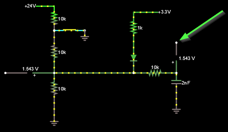
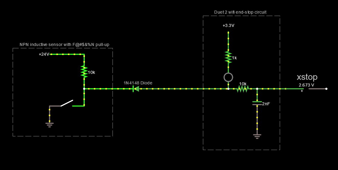
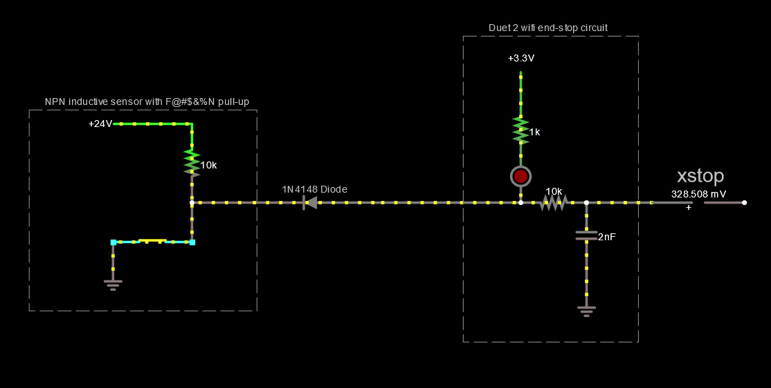
Hi Fredrick,
So I found that I did have some 1N4148 diodes, but tried this circuit instead (link to circuit simulator) of what you suggested (since I wasn't sure I 100% understood you).
In theory it should work great! in practice the voltage on the xstop pin is ~1.2v and I can't understand why!
Any clues here would be appreciated!
Thanks!
-
Hi
What is the output voltage of your device when you are reading the -1.2?
And where is the ground connection of your device connected?
Frederick
Printers: a small Utilmaker style, a small CoreXY and a E3D MS/TC setup. Various hotends. Using Duet 3 hardware running 3.4.6
-
How about you for a second entertain the possibility the sensor is faulty and list the full model number so we can look at the specs?
-
@fcwilt said in Endstop LED lighting, but DWC does not show them triggered:
Hi
What is the output voltage of your device when you are reading the -1.2?
And where is the ground connection of your device connected?
Frederick
Hi,
- When the sensor outputs 24v, input is at 3.3v (diode works!)
- When the sensor outputs 0v/GND, input is at 1.2v (positive voltage, I was using the tilda sign)
- GND is connected to endstop GND pin (because of wiring issues, all the endstop GNDS are connected to the E0-stop GND)
@bearer said in Endstop LED lighting, but DWC does not show them triggered:
How about you for a second entertain the possibility the sensor is faulty and list the full model number so we can look at the specs?
- I have 3 such sensors (delta axes), and all 3 show the same behavior.
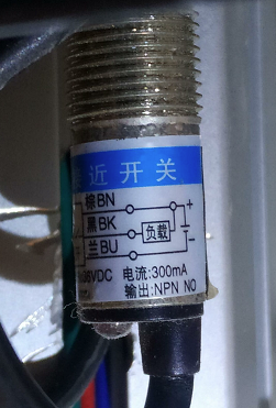
*** Disconnected from the board they pull down the voltage to 0.7v!** holy moly this is the problem! - Model number is marked as "CHE12-4NA-A710 (LJ12A3-4-Z/BX)"
- Apologies for not including this earlier!
I'll investigate this further to see if this is an issue in my setup or the sensor!
-
Well if the output of the device only goes to 0.7 volts when you add in the voltage drop across the diode you added you are up to about 1.4 volts.
You measured 1.2 volts - so that is about right.
If 1.2 volts is too high then you may have to use the multiple diode approach I mentioned since this would allow pulling down the input to the 0.7 volts of the device while preventing the device from pulling up the input higher than 4 diode drops - or 2.8 volts. Three diodes might be enough if 2.1 volts is sufficient to deactivate the input.
Frederick