Endstop LED lighting, but DWC does not show them triggered
-
If your device has an open collector output that connects to ground when active you should be able to treat it as a switch.
Have you verified that there is a voltage on the output when simply powered up and the output is not connected to anything?
Frederick
-
@fcwilt Hi, Yes I can confirm that when the sensor is disconnected, I get 24v when untriggered and 0v when triggered.
Do you mean just connect it as is to the board? won't that dump ~24v into the endstop circuit? I seem to remember reading that the LEDs can only handle ~8v....
-
No don't connect to the board.
I just wanted to know if the device had an pure open collector output (no pull-up resistor) - meaning it would show no voltage with the output disconnected.
What you can do to limit the voltage to the Duet is to connect 4 diodes (example 1N4148) in series, with the anode of the first one connected to the Duet input and the cathode of the last one connected to the Duet ground. This would limit the voltage at the input to roughly 2.8 volts but should be high enough to not activate the Duet input.
Then you would connect a 1K resistor from the output of your device to the Duet input. This resistor would limit the current to roughly 24 mA and protect the diodes but should be small enough in value to activate the Duet input.
The diode listed is rated to 200 mA so you could use, say, a 512 resistor if the 1K does not activate the Duet input.
Frederick
-
@Leav said in Endstop LED lighting, but DWC does not show them triggered:
Second, it's an NPN sensor:
you did start your thread saying it was a PNP sensor..
i'd perhaps suggest putting up the whole model number so you can get some help checking if it does have pull ups or have been damaged. Built in pull up on a NPN sensor is both uncommon and defeats the benefit of interfacing between different voltages.
-
@bearer said in Endstop LED lighting, but DWC does not show them triggered:
you did start your thread saying it was a PNP sensor..
Yup, forgot about that... to save face I can say I wasn't sure and added a question mark, but I could have just checked. Apologies.
@fcwilt said in Endstop LED lighting, but DWC does not show them triggered:
What you can do to limit the voltage to the Duet is to connect 4 diodes
That sounds... complicated, and I'm not sure I have any diodes. I think I'll try out alternative solutions first. might be time to just swap out to opto-endstops I have laying around somewhere.... hopefully they are 3.3v compatible...
@bearer said in Endstop LED lighting, but DWC does not show them triggered:
Built in pull up on a NPN sensor is both uncommon and defeats the benefit of interfacing between different voltages.
Thanks you for mentioning this! i'm not an EE but the pull up in that sensor did give me lots of headaches! would be so much simple if it was just not connected!!
-
Hi Fredrick,
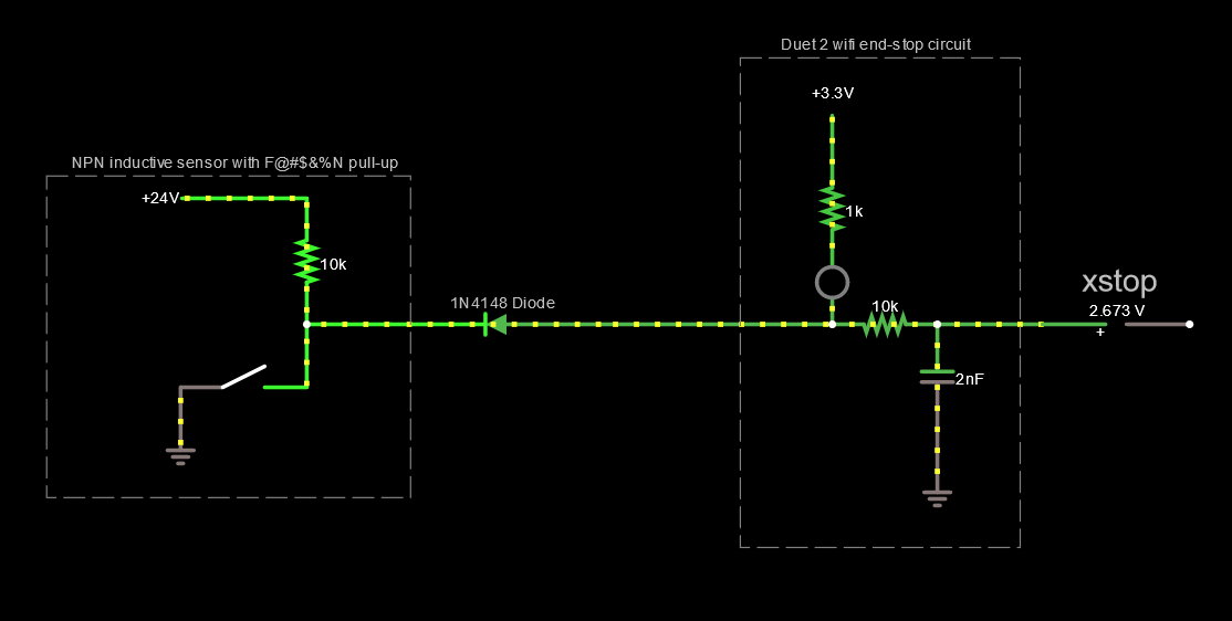
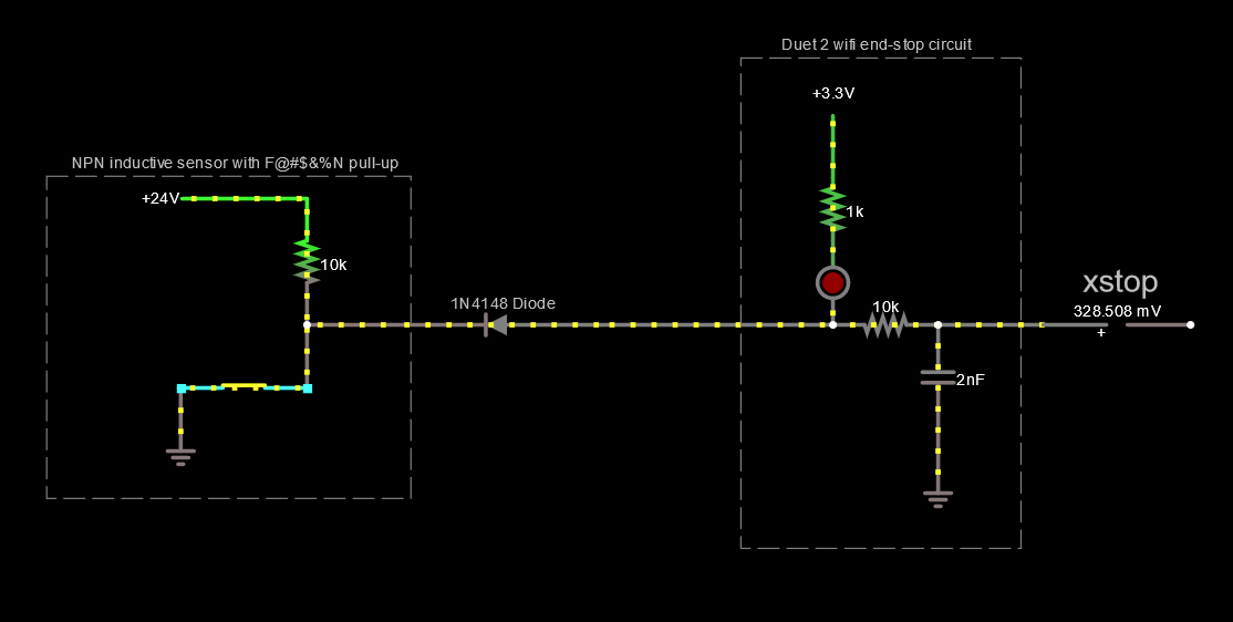
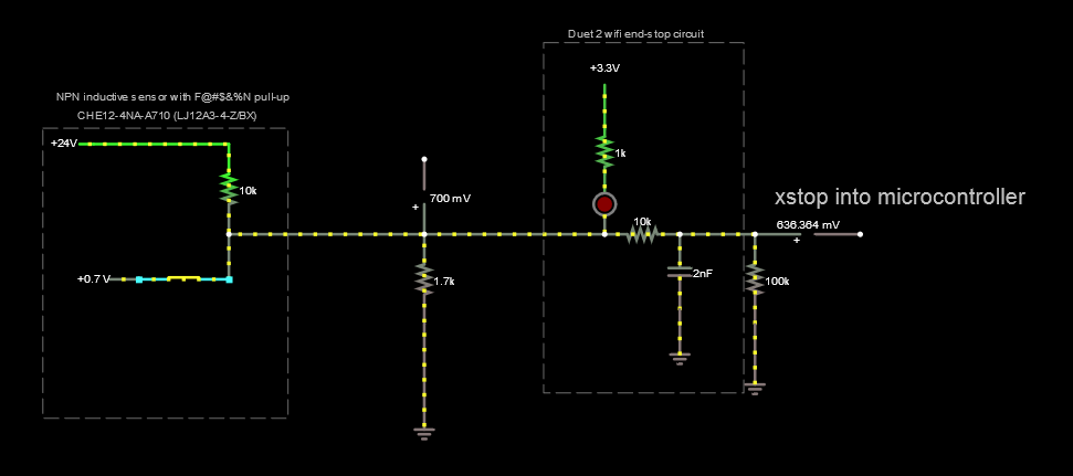
So I found that I did have some 1N4148 diodes, but tried this circuit instead (link to circuit simulator) of what you suggested (since I wasn't sure I 100% understood you).
In theory it should work great! in practice the voltage on the xstop pin is ~1.2v and I can't understand why!
Any clues here would be appreciated!
Thanks!
-
Hi
What is the output voltage of your device when you are reading the -1.2?
And where is the ground connection of your device connected?
Frederick
-
How about you for a second entertain the possibility the sensor is faulty and list the full model number so we can look at the specs?
-
@fcwilt said in Endstop LED lighting, but DWC does not show them triggered:
Hi
What is the output voltage of your device when you are reading the -1.2?
And where is the ground connection of your device connected?
Frederick
Hi,
- When the sensor outputs 24v, input is at 3.3v (diode works!)
- When the sensor outputs 0v/GND, input is at 1.2v (positive voltage, I was using the tilda sign)
- GND is connected to endstop GND pin (because of wiring issues, all the endstop GNDS are connected to the E0-stop GND)
@bearer said in Endstop LED lighting, but DWC does not show them triggered:
How about you for a second entertain the possibility the sensor is faulty and list the full model number so we can look at the specs?
- I have 3 such sensors (delta axes), and all 3 show the same behavior.
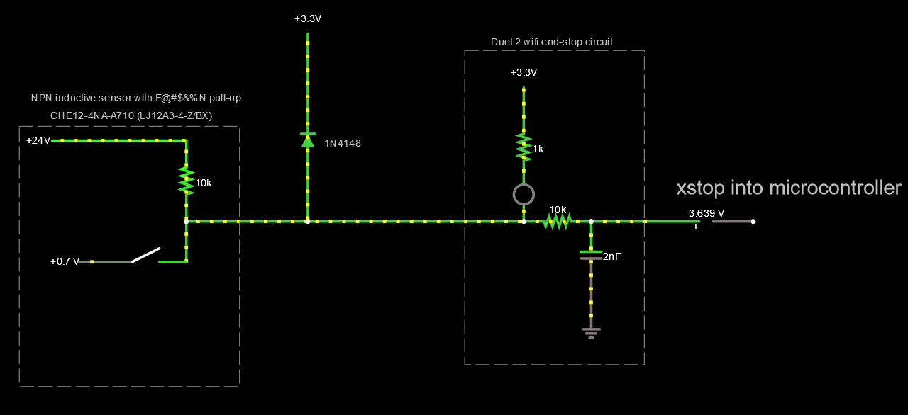
*** Disconnected from the board they pull down the voltage to 0.7v!** holy moly this is the problem! - Model number is marked as "CHE12-4NA-A710 (LJ12A3-4-Z/BX)"
- Apologies for not including this earlier!
I'll investigate this further to see if this is an issue in my setup or the sensor!
-
Well if the output of the device only goes to 0.7 volts when you add in the voltage drop across the diode you added you are up to about 1.4 volts.
You measured 1.2 volts - so that is about right.
If 1.2 volts is too high then you may have to use the multiple diode approach I mentioned since this would allow pulling down the input to the 0.7 volts of the device while preventing the device from pulling up the input higher than 4 diode drops - or 2.8 volts. Three diodes might be enough if 2.1 volts is sufficient to deactivate the input.
Frederick
-
@Leav said in Endstop LED lighting, but DWC does not show them triggered:
*** Disconnected from the board they pull down the voltage to 0.7v!** holy moly this is the problem!
i doubt it, 0.7v across the NPN junction on the sensor is well below the logic threshold MIN [0.8V, 0.3 × VDDIO] for the input pin; but it does mean that adding a diode (another PN junction) adds another 0.7v which brings you over the threshold. Maybe a schotty diode would do the trick, but not alot of margins.
unfortunately quick google search doesn't yield a datasheet that shows a pull up resistor in the sensor so you'd probably have to measure the value of the pull up and design your voltage divider accordingly.
-
@bearer @fcwilt
What do you think of this setup? (proposed on reddit).
Is there any chance of damaging the 3.3v rail with a setup like this?

-
Hi,
Well I would not try that approach without hearing from dc42 first.
Perhaps the multiple diode approach seems a bit of a kludge but it is safe.
Do you know what the logic threshold voltages are for this Duet input. Normally a logic 0 would be specified as being below some fixed voltage and a logic 1 would be defined as being above some fixed voltage.
With a supply voltage of 3.3 it is possible that 2.1 (three diodes) would qualify as a logic 1.
So we are only talking about two additional diodes.
There is a type of diode called a zener which comes in different voltage ratings which could be used in your case to insure the input doesn't exceed a certain value.
I saw an assortment on Amazon that had numerous low voltage devices:
Chanzon 34 Values 0.5W Zener Diode Assorted Kit (2V 2.2V 2.4V 2.7V 3V 3.3V...) plus other much higher values. It was $7 for 34 diodes.
If you didn't mind using an LED they have different forward voltage drops depending on color. I believe I have a batch of white ones rated at 3 volts.
Frederick
-
@fcwilt said in Endstop LED lighting, but DWC does not show them triggered:
Do you know what the logic threshold voltages are for this Duet input.
@bearer said in Endstop LED lighting, but DWC does not show them triggered:
the logic threshold MIN [0.8V, 0.3 × VDDIO] for the input pin
(high side is MIN [2.0V, 0.7 × VDDIO])
-
@bearer said in Endstop LED lighting, but DWC does not show them triggered:
the logic threshold MIN [0.8V, 0.3 × VDDIO] for the input pin
Normally there would be two specs - one for a logic 0 and one for a logic 1.
Do you have a link to this info?
Thanks.
Frederick
-
-
-
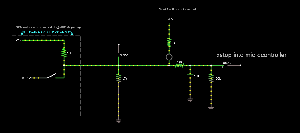
Solved it! Thanks everyone for your help and guidance.
For posterity, I ended up using a pull down resistor of 1.7K, which balances the effects of:
- pull up in sensor
- pull up in Duet
-
@Leav said in Endstop LED lighting, but DWC does not show them triggered:
For posterity, I ended up using a pull down resistor of 1.7K
That is the standard way to use a PNP-output sensor. It's the same as for a Z probe (see https://duet3d.dozuki.com/Wiki/Connecting_a_Z_probe#Section_PNP_output_normally_open_inductive_or_capacitive_sensor) except that you need a lower value pulldown resistor, because of the pullup resistor in the Duet.
The output of an NPN sensor can be connected directly to the endstop input on all modern Duets, and should work that way.
-
@dc42 said in Endstop LED lighting, but DWC does not show them triggered:
The output of an NPN sensor can be connected directly to the endstop input on all modern Duets, and should work that way.
If I understand correctly, I think I have a very weird "NPN-ish" sensor, since it has a pull-up internally. connecting it directly would connect 24v to the 3.3v rail, which I understand is not a good thing, even with all the resistors in the way.