Issues with IR Probe offset
-
New ir probe installed and having issues with the offset, when i try to print the nozzle drags along the bed. I have Done all i can from the test and calibrate the z probe without luck. I am running the duet 2 wifi on my ender 5 pro, here are my files:
; Configuration file for Duet WiFi (firmware version 3)
; executed by the firmware on start-up
;
; generated by RepRapFirmware Configuration Tool v3.1.3 on Sun Jul 05 2020 20:32:26 GMT-0500 (Central Daylight Time)

; General preferences
G90                                                ; send absolute coordinates...
M83                                                ; ...but relative extruder moves
M550 P"Schaal3DPrinter"                            ; set printer name

; Network
M552 S1                                            ; enable network
M586 P0 S1                                         ; enable HTTP
M586 P1 S1                                         ; enable FTP
M586 P2 S1                                         ; enable Telnet

; Drives
M569 P0 S0                                         ; physical drive 0 goes forwards
M569 P1 S0                                         ; physical drive 1 goes forwards
M569 P2 S0                                         ; physical drive 2 goes forwards
M569 P3 S0                                         ; physical drive 3 goes forwards
M584 X0 Y1 Z2 E3                                   ; set drive mapping
M350 X16 Y16 Z16 E16 I1                            ; configure microstepping with interpolation
M92 X80.00 Y80.00 Z800.00 E130                   ; set steps per mm
M566 X900.00 Y900.00 Z12.00 E120.00                ; set maximum instantaneous speed changes (mm/min)
M203 X6000.00 Y6000.00 Z180.00 E1200.00            ; set maximum speeds (mm/min)
M201 X500.00 Y500.00 Z20.00 E250.00                ; set accelerations (mm/s^2)
M906 X800 Y800 Z800 E800 I30                       ; set motor currents (mA) and motor idle factor in per cent
M84 S30                                            ; Set idle timeout

; Axis Limits
M208 X0 Y0 Z0 S1                                   ; set axis minima
M208 X225 Y225 Z300 S0                             ; set axis maxima

; Endstops
M574 X2 S1 P"xstop" 							   ; configure active-high endstop for low end on X via pin xstop
M574 Y2 S1 P"ystop" 							   ; configure active-high endstop for low end on Y via pin ystop
M574 Z1 S1 P"zstop"                                ; configure active-high endstop for high end on Z via pin zstop

; Z-Probe
M558 P1 C"^zprobe.in" H5 F120 T6000                 ; set Z probe type to unmodulated and the dive height + speeds
G31 P500 X-50 Y0 Z0.195                              ; set Z probe trigger value, offset and trigger height
M557 X10:175 Y10:215 P8                           ; define mesh grid

; Heaters
M308 S0 P"bedtemp" Y"thermistor" T100000 B4138     ; configure sensor 0 as thermistor on pin bedtemp
M950 H0 C"bedheat" T0                              ; create bed heater output on bedheat and map it to sensor 0
M307 H0 B1 S1.00                                   ; enable bang-bang mode for the bed heater and set PWM limit
M140 H0                                            ; map heated bed to heater 0
M143 H0 S120                                       ; set temperature limit for heater 0 to 120C
M308 S1 P"e0temp" Y"thermistor" T100000 B4138      ; configure sensor 1 as thermistor on pin e0temp
M950 H1 C"e0heat" T1                               ; create nozzle heater output on e0heat and map it to sensor 1
M307 H1 B0 S1.00                                   ; disable bang-bang mode for heater  and set PWM limit

; Fans
M950 F0 C"fan0" Q500                               ; create fan 0 on pin fan0 and set its frequency
M106 P0 S0 H-1                                     ; set fan 0 value. Thermostatic control is turned off
M950 F1 C"fan1" Q500                               ; create fan 1 on pin fan1 and set its frequency
M106 P1 S1 H1 T45                                  ; set fan 1 value. Thermostatic control is turned on

; Tools
M563 P0 D0 H1 F0                                   ; define tool 0
G10 P0 X0 Y0 Z0                                    ; set tool 0 axis offsets
G10 P0 R0 S0                                       ; set initial tool 0 active and standby temperatures to 0C

; Custom settings are not defined

; Miscellaneous
M911 S10 R11 P"M913 X0 Y0 G91 M83 G1 Z3 E-5 F1000" ; set voltage thresholds and actions to run on power loss
M501
; homeall.g ; called to home all axes ; ; generated by RepRapFirmware Configuration Tool v3.1.3 on Sun Jul 05 2020 20:32:27 GMT-0500 (Central Daylight Time) G91 ; relative positioning G1 H2 Z5 F6000 ; lift Z relative to current position G1 H1 X+250 Y+250 F1800 ; move quickly to X and Y axis endstops and stop there (first pass) G1 H2 X-5 Y-5 F6000 ; go back a few mm G1 H1 X+230 Y+230 F360 ; move slowly to X and Y axis endstops once more (second pass) G90 ; absolute positioning G1 X150 Y150 F6000 ; move probe to center of bed G30 ; probe the bed ;G1 H1 Z305 F360 ; move Z up stopping at the endstop ;G1 H1 Z-320 F360 ; move Z stopping at the endstop ;G90 ; absolute positioning ; Uncomment the following lines to lift Z after probing ;G91 ; relative positioning ;G1 Z5 F100 ; lift Z relative to current position ;G90 ; absolute positioning; homex.g ; called to home the X axis ; ; generated by RepRapFirmware Configuration Tool v3.1.3 on Sun Jul 05 2020 20:32:27 GMT-0500 (Central Daylight Time) G91 ; relative positioning G1 H2 Z5 F6000 ; lift Z relative to current position G1 H1 X+250 F1800 ; move quickly to X axis endstop and stop there (first pass) G1 H2 X-5 F6000 ; go back a few mm G1 H1 X+230 F360 ; move slowly to X axis endstop once more (second pass) G1 H2 Z-5 F6000 ; lower Z again G90 ; absolute positioning; homez.g ; called to home the Z axis ; ; generated by RepRapFirmware Configuration Tool v3.1.3 on Sun Jul 05 2020 20:32:27 GMT-0500 (Central Daylight Time) G91 ; relative positioning G1 H2 Z5 F6000 ; lift Z relative to current position G90 ; absolute positioning G1 X150 Y150 F6000 ; move probe to center of bed G30 ; probe the bed ;G1 H1 Z305 F1800 ; move Z up until the endstop is triggered ;G1 H1 Z-320 F360 ; move Z stopping at the endstop ;G90 ; absolute positioning ; Uncomment the following lines to lift Z after probing ;G91 ; relative positioning ;G1 Z5 F100 ; lift Z relative to current position ;G90 ; absolute positioning; homey.g ; called to home the Y axis ; ; generated by RepRapFirmware Configuration Tool v3.1.3 on Sun Jul 05 2020 20:32:27 GMT-0500 (Central Daylight Time) G91 ; relative positioning G1 H2 Z5 F6000 ; lift Z relative to current position G1 H1 Y+230 F1800 ; move quickly to Y axis endstop and stop there (first pass) G1 H2 Y-5 F6000 ; go back a few mm G1 H1 Y+230 F360 ; move slowly to Y axis endstop once more (second pass) G1 H2 Z-5 F6000 ; lower Z again G90 ; absolute positioning7/28/2020, 5:18:15 PM M122 === Diagnostics === RepRapFirmware for Duet 2 WiFi/Ethernet version 3.1.1 running on Duet WiFi 1.02 or later Board ID: 08DLM-996RU-N8PS4-7J1FJ-3SJ6S-189BQ Used output buffers: 3 of 24 (12 max) === RTOS === Static ram: 27980 Dynamic ram: 93932 of which 44 recycled Exception stack ram used: 568 Never used ram: 8548 Tasks: NETWORK(ready,384) HEAT(blocked,1224) MAIN(running,1840) IDLE(ready,80) Owned mutexes: WiFi(NETWORK) === Platform === Last reset 00:50:08 ago, cause: software Last software reset at 2020-07-28 16:28, reason: User, spinning module GCodes, available RAM 8852 bytes (slot 1) Software reset code 0x0003 HFSR 0x00000000 CFSR 0x00000000 ICSR 0x0041f000 BFAR 0xe000ed38 SP 0xffffffff Task MAIN Error status: 0 MCU temperature: min 30.2, current 31.0, max 31.9 Supply voltage: min 23.9, current 24.1, max 24.3, under voltage events: 0, over voltage events: 0, power good: yes Driver 0: standstill, SG min/max 0/324 Driver 1: standstill, SG min/max 87/298 Driver 2: standstill, SG min/max not available Driver 3: standstill, SG min/max not available Driver 4: standstill, SG min/max not available Date/time: 2020-07-28 17:18:11 Cache data hit count 4294967295 Slowest loop: 17.01ms; fastest: 0.12ms I2C nak errors 0, send timeouts 0, receive timeouts 0, finishTimeouts 0, resets 0 === Storage === Free file entries: 10 SD card 0 detected, interface speed: 20.0MBytes/sec SD card longest read time 4.1ms, write time 2.1ms, max retries 0 === Move === Hiccups: 0(0), FreeDm: 169, MinFreeDm: 166, MaxWait: 139149ms Bed compensation in use: mesh, comp offset 0.000 === MainDDARing === Scheduled moves: 348, completed moves: 348, StepErrors: 0, LaErrors: 0, Underruns: 0, 0 CDDA state: -1 === AuxDDARing === Scheduled moves: 0, completed moves: 0, StepErrors: 0, LaErrors: 0, Underruns: 0, 0 CDDA state: -1 === Heat === Bed heaters = 0 -1 -1 -1, chamberHeaters = -1 -1 -1 -1 === GCodes === Segments left: 0 Movement lock held by null HTTP is idle in state(s) 0 Telnet is idle in state(s) 0 File is idle in state(s) 0 USB is idle in state(s) 0 Aux is idle in state(s) 0 Trigger is idle in state(s) 0 Queue is idle in state(s) 0 Daemon is idle in state(s) 0 Autopause is idle in state(s) 0 Code queue is empty. === Network === Slowest loop: 80.05ms; fastest: 0.00ms Responder states: HTTP(2) HTTP(0) HTTP(0) HTTP(0) FTP(0) Telnet(0), 0 sessions HTTP sessions: 1 of 8 - WiFi - Network state is active WiFi module is connected to access point Failed messages: pending 0, notready 0, noresp 0 WiFi firmware version 1.23 WiFi MAC address bc:dd:c2:2d:67:97 WiFi Vcc 3.39, reset reason Unknown WiFi flash size 4194304, free heap 21240 WiFi IP address 10.1.2.149 WiFi signal strength -53dBm, reconnections 0, sleep mode modem Socket states: 4 0 0 0 0 0 0 0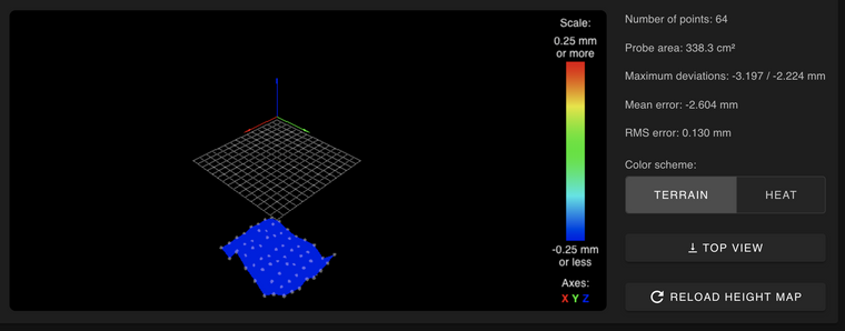
7/27/2020, 8:02:10 PM Upload of config.g successful after 0s 7/27/2020, 8:01:37 PM G30 S-1 Stopped at height 0.195 mm 7/27/2020, 8:01:23 PM G1 Z5 7/27/2020, 8:01:14 PM G30 S-1 Stopped at height 0.196 mm 7/27/2020, 8:00:58 PM G1 Z5 7/27/2020, 8:00:45 PM G30 S-1 Stopped at height 0.195 mm 7/27/2020, 8:00:25 PM G1 Z5 7/27/2020, 7:59:46 PM G30 S-1 Stopped at height 0.192 mm -
@agent0810 your M557 starts left of the M208 X minimum, because you must take the G31 offset into account, so please set M557 X value higher, minimum 50. So the probe may have missed the bed at the first probe point.
-
@JoergS5 so something like X50:175?
-
@agent0810 yes, but to be sure the ir sensor has a good signal, I would start with 60 (depends on your endstop position). X max can be larger, but better test first whether it's the reason.
-
@JoergS5 well that helped a bit. :). .... any other recomendations?
-
@agent0810 I have only the recommendation to make the bed parallel to the x and y axes before starting with mesh compensation. I don' t see errors in the config at the moment.
First I would try to find out whether the bed is uneven or the x axis is bent. ( nice would be a hair lineal) -
@JoergS5 thank you for the help!
-
@agent0810 our posts crossed, please see my addition.
You're welcome, good luck!
-
@JoergS5
ive kinda gone over that as much as i can. all the bars seem to be level and parallel to the bed. im not sure what i could be doing wrong. i ve read alot of artices, alot of advice and help from people here, and youtube videos. i just cant seem to get it leveled ..... -
@agent0810 one possibility is bending due to temperature. Do you heat the bed and have screws?
-
@JoergS5
yea i try to do this all when the bed is heated. its a ender 5 pro so it has 4 big black screws on the bottom. -
@agent0810 try to loosen three screws and one fixed. This allows thermal expansion. The bed could be bent permanently already however. But its worth a try.
Loosen in the sense it can expand in xy, but not in z direction.
-
not sure what you mean int the xy but not the z direction
-
@agent0810 the screws fix xyz. If you loosen a bit, the bed can expand in xy directions, but not up or down.
-
@JoergS5 hmmmmm when i untighten the screws the bed goes up, when i tighten its pulled down.
-
@agent0810 thats a signal that you bend the bed with the screws.....
-
@JoergS5 soooooo i need a new bed?
-
@agent0810 not necessarily, you only need to install it even and without force
The best information I know is https://drmrehorst.blogspot.com/2017/07/3-point-print-bed-leveling-vs-4-point.html?m=1 and other articles on his page.
-
@agent0810 said in Issues with IR Probe offset:
@JoergS5 so something like X50:175?
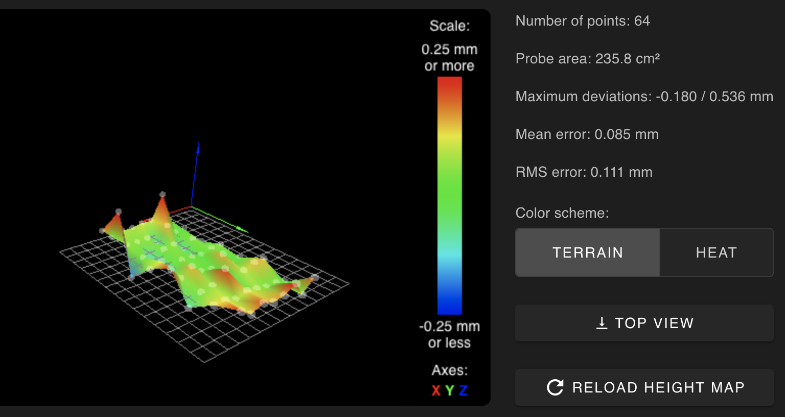
I think we already established the correct mesh in your previous thread. In your image from your first post you can see that the probe was able to reach those points, and on your resulting image you're limited to just a strip in the middle now.
I'd try your original M557 values and redo the mesh again. I think the huge offset on your first attempt was an anomaly from running G29 without a fresh homing first.
-
@agent0810 I was not aware of the other thread. If you optimized M557 already, the original value is no problem of course (because the endstop/M208 will not be at the edge of the print bed in your case, I suspect. Just be careful not to touch/damage the sensor with the brackets).
Your top layer is fiexed by brackets, so this could be the reason for the print area to be wavy. You should think about the design of the print bed according to the mrehorst blogs.
My recommendations about hair lineal was halfway serious. The idea is that with two unknowns (is the X axis uneven or the print bed?) it's difficult to know what to make better. So a hair angle (to measure perpendiculary also) is a valuable tool.
I took the best tolerance DIN 875/00. (Best would be 300 mm in your case, but they are expensive) One can measure the angle between X and Y also.