Stuck in spin loop, spinning module G-Codes
-
Good morning,
Here I leave the config.g and triggers2 and 3
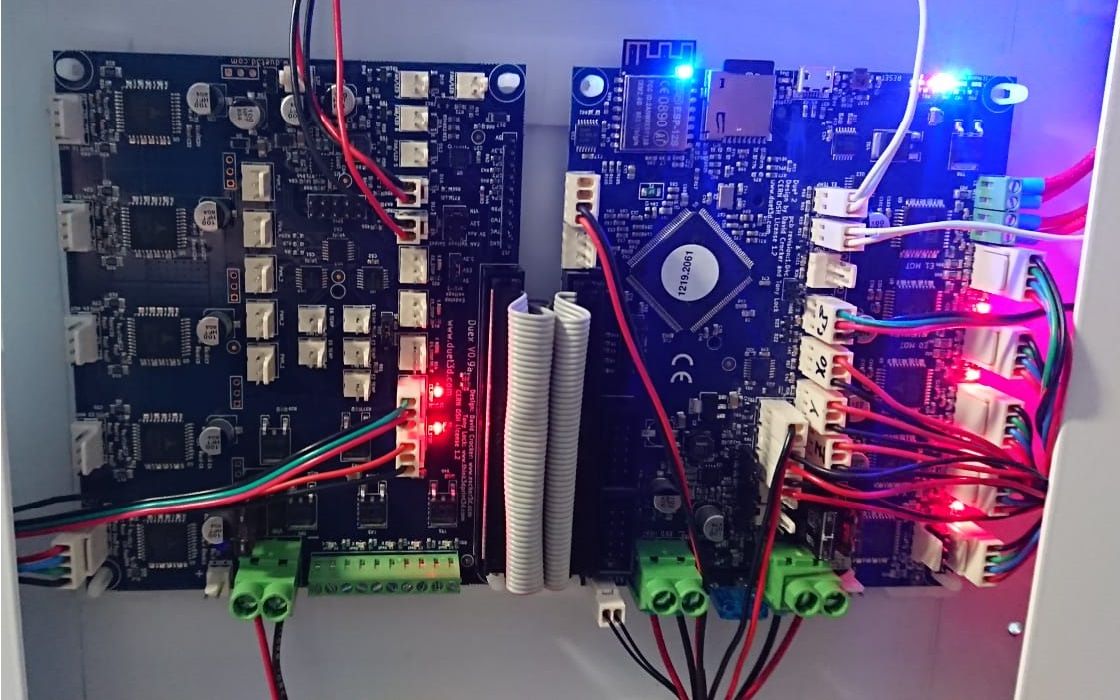
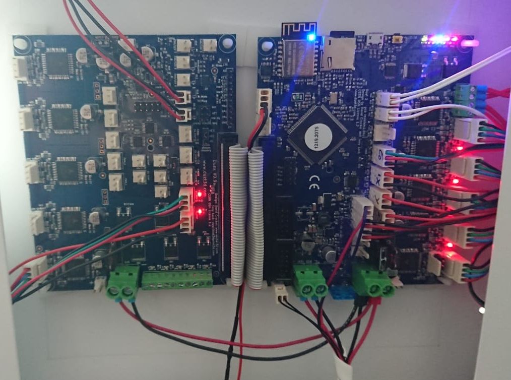
I leave you an image of how the Duex is connected, it is powered directly from the 24V source
; General preferences G90 ; Enviar coordenadas absolutas... M83 ; ...pero el extrusor relativo se mueve M550 P"IDEX" ; Establecer el nombre de la impresora ; Network M552 S1 ; Enable network M586 P0 S1 ; Enable HTTP M586 P1 S0 ; Disable FTP M586 P2 S0 ; Disable Telnet ; Controladores M569 P0 S1 ; El impulso físico X va hacia Snnn: 0 = hacia atrás, 1 = hacia adelante M569 P1 S0 ; El impulso físico Y va hacia Snnn: 0 = hacia atrás, 1 = hacia adelante M569 P2 S1 ; El impulso físico Z va hacia Snnn: 0 = hacia atrás, 1 = hacia adelante M569 P3 S0 ; El impulso físico E0 va hacia Snnn: 0 = hacia atrás, 1 = hacia adelante M569 P4 S1 ; El impulso físico E1 va hacia Snnn: 0 = hacia atrás, 1 = hacia adelante M569 P5 S1 ; El impulso físico U va hacia Snnn: 0 = hacia atrás, 1 = hacia adelante M584 X0 Y1 Z2 U5 E3:4 ; Establecer el mapeo de la unidad de disco M350 Z32 I0 ; Configurar los micro-pasos sin interpolación M350 X16 Y16 U16 E16 I1 ; Configurar los micro-pasos con interpolación M92 X100.00 Y100.00 Z800.00 U100 E150.00:150.00 ; Establecer pasos por mm M566 X900.00 Y900.00 Z12.00 U900.00 E8000.00:8000.00 ; Establecer los máximos cambios de velocidad instantánea (mm/min) M203 X9000.00 Y9000.00 Z3000.00 U9000.00 E9000.00:9000.00 ; Establecer las velocidades máximas (mm/min) M201 X1800.00 Y1800.00 Z24.00 U1800.00 E8000.00:8000.00 ; Establecer las aceleraciones (mm/s^2) M906 X320 Y1360 Z320 U320 E1360:1360 I30 ; Establecer las corrientes del motor (mA) y el factor de ralentí del motor en porcentaje M84 S60 ; Establecer el tiempo de espera para desactivar motores ; Límites del eje M208 X0 Y0 Z0 U60 S1 ; Establecer los mínimos del eje M208 X240 Y220 Z200 U300 S0 ; Establecer los máximos de los ejes ; Finales de carrera M574 X1 S1 P"xstop" ; Configurar activo-alto para el extremo inferior en X a través del pin xstop M574 Y1 S1 P"ystop" ; Configurar activo-alto para el extremo inferior en Y a través del pin ystop M574 Z1 S1 P"zstop" ; Configurar activo-alto para el extremo inferior en Z a través del pin zstop M574 U2 S1 P"duex.e2stop" ; Configurar activo-alto para el extremo inferior en U a través del pin e0stop M950 J1 C"e0stop" ; Configura la entrada 1 usa el pin e0stop M950 J2 C"duex.e3stop" ; Configura la entrada 1 usa el pin duex.e2stop M581 P1 T2 R1 ; Configurar disparador externo Tnn: 0= M112, 1= M25, >1(#) = se ejecute el archivo macro sys / trigger#.g. M581 P2 T3 R1 ; Configurar disparador externo Tnn: 0= M112, 1= M25, >1(#) = se ejecute el archivo macro sys / trigger#.g. ;NOTA: Complemente en el Star-code (M582 T#; Chequea si hay presencia de filamento) ; Sonda Z M558 P0 H5 F120 T6000 ; Desactivar la sonda Z pero ajustar la altura de inmersión, la velocidad de la sonda y la velocidad de desplazamiento M557 X15:215 Y15:195 S20 ; Definir la red de malla ; Calentadores M308 S0 P"bedtemp" Y"thermistor" T100000 B4138 ; Configurar el sensor 0 como termistor en el pin bedtemp M950 H0 C"bedheat" T0 ; Crear la salida del calentador de la cama en el calentador de la cama y asignarlo al sensor 0 M143 H0 S150 ; Establecer el límite de temperatura para el calentador de 0 a 150C M307 H0 B0 S1.00 ; Habilitar el modo bang-bang para el calentador de cama y establecer el límite PWM M570 H0 P30 T15 S0 ; Configurar la detección de fallas del calentador M140 H0 ; Mapa cama calefactora a calefactor 0 M308 S1 P"e0temp" Y"thermistor" R4700 T100000 B3950 ; Configurar el sensor 1 como termistor en el pin e0temp M950 H1 C"e0heat" T1 ; Crear la salida del calentador de la boquilla en e0heat y asignarla al sensor 1 M143 H1 S300 ; Establecer el límite de temperatura para el calentador de 1 a 350C M307 H1 B0 S1.00 ; Deshabilitar el modo bang-bang para el calentador y establecer el límite PWM M308 S2 P"e1temp" Y"thermistor" R4700 T100000 B3950 ; Configurar el sensor 2 como termistor en el pin e1temp M950 H2 C"e1heat" T2 ; Crear la salida del calentador de la boquilla en e1heat y asignarla al sensor 2 M143 H2 S300 ; Establecer el límite de temperatura para el calentador de 2 a 350C M307 H2 B0 S1.00 ; Deshabilitar el modo bang-bang para el calentador y establecer el límite PWM M302 P0 S160 R160 ; Pnnn Estado de permiso, Snnn Temp. mín. extrusión, Rnnn Temp. mín. retracción ; Ventiladores M950 F0 C"fan0" Q500 T1 ; Crear el ventilador 0 en el pin fan0 y establecer su frecuencia M106 P0 C"Frontal_1" S1 H1 T45 ; Ponga el nombre y el valor del ventilador 0. El control termostático está activado M950 F1 C"fan1" Q500 ; Crear el ventilador 1 en la clavija fan1 y establecer su frecuencia M106 P1 C"Ventilador_1" S0 H-1 ; Ajustar el valor del ventilador 1. El control termostático está apagado M950 F2 C"fan2" Q500 ; Crea la salida fan2 para la tira LED a 500Hz M106 P2 C"LED" S255 ; Activa el ventilador a 255 M950 F3 C"duex.fan3" Q500 T2 ; Crear el ventilador 0 en el pin fan0 y establecer su frecuencia M106 P3 C"Frontal_2" S1 H2 T45 ; Ponga el nombre y el valor del ventilador 0. El control termostático está activado M950 F4 C"duex.fan4" Q500 ; Crear el ventilador 1 en la clavija fan1 y establecer su frecuencia M106 P4 C"Ventilador_2" S0 H-1 ; Ajustar el valor del ventilador 1. El control termostático está apagado ; Herramientas M563 P0 S"DART1" D0 H1 F0:1 ; P = Definir la herramienta 0, D = Extrusora 0, H = Calentador 1, F = Ventilador 0 y 1 M563 P1 S"DART2" D1 H2 X3 F3:4 ; P = Definir la herramienta 1, D = Extrusora 1, H = Calentador 2, F = Ventilador 3 y 4 M563 P2 S"DART12" D0:1 H1:2 X0:3 F0:1:3:4 ; Cree una herramienta que imprima 2 copias del objeto usando ambos carros G10 P0 X0 Y0 U0 Z0 ; Establecer la herramienta 0 desplazamientos del eje ;G10 P1 Y0 U1.2 Z0 ;MODIFICA U e Y si es necesario ; Establecer la herramienta 1 desplazamientos del eje G10 P1 Y0 U1.2 Z0 ;MODIFICA U e Y si es necesario ; Establecer la herramienta 1 desplazamientos del eje G10 P2 X0 Y0 U-150 ; Establecer la herramienta 2 desplazamientos del eje G10 P0 R0 S0 ; Establecer la herramienta inicial 0 activa y las temperaturas de espera a 0C G10 P1 R0 S0 ; Establecer la herramienta inicial 1 activa y las temperaturas de espera a 0C G10 P2 R0 S0 ; Establecer la herramienta inicial 2 activa y las temperaturas de espera a 0C ; LCD M575 P1 S1 B57600 ; Establecer parámetros de comunicación serie ; Siempre al final M912 P0 S-4 ; Corrije la temperatura de la CPU M501 ; Lee parámetros almacenados. Establezce los parámetros activos a los almacenados en sys / config-override.g en la tarjeta SD M911 S22 R23 P"M913 X0 Y0 Z0 E0" ; Configure el guardado automático en la pérdida de energía T0 P0 ; Seleccion de herramienta por defecto ;Sensor de Filamento Trigger2 G4 S1 if {sensors.gpIn[1].value = 1} ; M25 ; M291 R"Pausa" P"No se detecta presencia de filamento" S3 T0 ; else ;Sensor de Filamento Trigger3 G4 S1 if {sensors.gpIn[2].value = 1} ; M25 ; M291 R"Pausa" P"No se detecta presencia de filamento" S3 T0 ; else -
Hi,
Did you read this about power wiring when having a Duex5?
Important! You must have a reliable low-resistance connection between the negative (ground) terminals of the two VIN terminal blocks. Failure to do so may result in high currents flowing in the ground connectors of the ribbon cable and may cause damage to the Duet 2 or Duex. Preferably, make this connection using either solid core wire, or stranded core wire with ferrules of the correct size crimped on securely. Re-tighten the terminal block screws regularly for the first few days of use, to make sure there is no creep in the wires causing the screws to become loose.
Frederick
-
Hello,
I would say yes, the Vin input is with a proper wire and both motherboards are connected directly to the outputs of a MeanWell source, the data bus is the one that comes with the duex5 electronics and during the operation it does not seem to heat
The electronics restart if any temperature is reached?
-
-
Yes I believe you will need to correct your power and ground connection between the duet and duex as shown by @fcwilt and described here: https://duet3d.dozuki.com/Wiki/Duex2_and_Duex5_Features#Section_Wiring
-
I have made the changes in 4 machines (all of them identical) but two of them have already stopped, in one of which has stopped, I put a power supply of higher capacity to test it and also stopped
Could the problem be the G-code or something in Simplify??
It does not always fail. If I reboot the printer, most of the time, the first printing works well but the next one has the problem. Working with the same G-Code.
Thanks!
-
It might be worth trying a fresh SD card.
-
Hello,
I have not tried to change the micro SD, but it is a bit extrange to have the micro SD card damaged in 4 duet in different machines, no?
In one machine I introduce M122 and this is what appears: "hard fault, spinning module none". This worries me even more, since this one hasn't stopped for a few days.
Any idea or recommendation to try to solve both problems (the stops and the last message)?
M122
=== Diagnostics ===
RepRapFirmware for Duet 2 WiFi/Ethernet version 3.1.1 running on Duet WiFi 1.02 or later + DueX5
Board ID: 08DLM-996RU-N85T0-6J9FA-3SD6R-1VS3N
Used output buffers: 3 of 24 (24 max)
=== RTOS ===
Static ram: 27980
Dynamic ram: 95924 of which 44 recycled
Exception stack ram used: 592
Never used ram: 6532
Tasks: NETWORK(ready,268) HEAT(blocked,1124) DUEX(suspended,160) MAIN(running,1732) IDLE(ready,80)
Owned mutexes: WiFi(NETWORK)
=== Platform ===
Last reset 41:48:37 ago, cause: watchdog
Last software reset at 2020-07-29 15:38, reason: Hard fault, spinning module none, available RAM 0 bytes (slot 3)
Software reset code 0x4071 HFSR 0x40000000 CFSR 0x00008200 ICSR 0x00000803 BFAR 0x8688b5b0 SP 0x2001ff7c Task MAIN
Stack: 00452be1 00401cc8 01030000 00000006 2001ffb8 00000000 200088b0 2000565c 004569cd 20000088 20005894
Error status: 0
MCU temperature: min 35.6, current 40.2, max 49.6
Supply voltage: min 23.7, current 24.1, max 24.4, under voltage events: 0, over voltage events: 0, power good: yes
Driver 0: standstill, SG min/max 0/1023
Driver 1: standstill, SG min/max 0/1023
Driver 2: standstill, SG min/max 0/580
Driver 3: standstill, SG min/max 0/1023
Driver 4: standstill, SG min/max 0/1023
Driver 5: standstill, SG min/max 0/1023
Driver 6: standstill, SG min/max not available
Driver 7: standstill, SG min/max not available
Driver 8: standstill, SG min/max not available
Driver 9: standstill, SG min/max not available
Date/time: 2020-07-31 09:28:20
Cache data hit count 4294967295
Slowest loop: 207.17ms; fastest: 0.14ms
I2C nak errors 0, send timeouts 0, receive timeouts 0, finishTimeouts 0, resets 0
=== Storage ===
Free file entries: 10
SD card 0 detected, interface speed: 20.0MBytes/sec
SD card longest read time 5.0ms, write time 160.3ms, max retries 0
=== Move ===
Hiccups: 0(0), FreeDm: 169, MinFreeDm: 106, MaxWait: 59465336ms
Bed compensation in use: none, comp offset 0.000
=== MainDDARing ===
Scheduled moves: 465950, completed moves: 465950, StepErrors: 0, LaErrors: 0, Underruns: 0, 0 CDDA state: -1
=== AuxDDARing ===
Scheduled moves: 0, completed moves: 0, StepErrors: 0, LaErrors: 0, Underruns: 0, 0 CDDA state: -1
=== Heat ===
Bed heaters = 0 -1 -1 -1, chamberHeaters = -1 -1 -1 -1
Heater 0 is on, I-accum = 0.0
Heater 1 is on, I-accum = 0.5
=== GCodes ===
Segments left: 0
Movement lock held by null
HTTP is idle in state(s) 0
Telnet is idle in state(s) 0
File is idle in state(s) 0
USB is idle in state(s) 0
Aux is idle in state(s) 0
Trigger is idle in state(s) 0
Queue is idle in state(s) 0
Daemon is idle in state(s) 0
Autopause is idle in state(s) 0
Code queue is empty.
=== Network ===
Slowest loop: 206.20ms; fastest: 0.00ms
Responder states: HTTP(0) HTTP(0) HTTP(0) HTTP(0) FTP(0) Telnet(0), 0 sessions
HTTP sessions: 2 of 8- WiFi -
Network state is active
WiFi module is connected to access point
Failed messages: pending 0, notready 0, noresp 0
WiFi firmware version 1.23
WiFi MAC address[0_1596182504353_My Config.zip](Uploading 100%)
WiFi Vcc 3.40, reset reason Unknown
WiFi flash size 4194304, free heap 20632
WiFi IP address 192.168.1.139
WiFi signal strength -73dBm, reconnections 1, sleep mode modem
Socket states: 0 0 0 0 0 0 0 0
=== DueX ===
Read count 181584, 72.38 reads/min
My SYS: (without firmware)
bed.g
cancel.g
config.g
config-override.g
dwc2settings.json
gfinal.g
ginicioT0.g
ginicioT1.g
ginicioT2.g
ginicioT3.g
homeall.g
homeu.g
homex.g
homey.g
homez.g
pause.g
resume.g
resurrect-prologue.g
sleep.g
stop.g
tfree0.g
tfree1.g
tfree2.g
tpost0.g
tpost1.g
tpost2.g
tpre0.g
tpre1.g
tpre2.g
trigger2.g
trigger3.g - WiFi -
-
-
@Phaedrux said in Stuck in spin loop, spinning module G-Codes:
It might be worth trying a fresh SD card.
Four SD cards formatted and still stopping.
As soon as I have a new card, I will try it.
Any other ideas or suggestions?Many thanks in advance!
-
Thanks for the additional information and config files. I haven't had a chance to dig into all of them yet. It may be beyond me to give you any resolution. DC42 may have to take a look when he returns next week. In the meantime please continue to report a M122 if it stops again.
-
This machine hasn't stopped for two days, but it's already stopped
M122
=== Diagnostics ===
RepRapFirmware for Duet 2 WiFi/Ethernet version 3.1.1 running on Duet WiFi 1.02 or later + DueX5
Board ID: 08DLM-996RU-N85T0-6J9FA-3SD6R-1VS3N
Used output buffers: 14 of 24 (24 max)
=== RTOS ===
Static ram: 27980
Dynamic ram: 95524 of which 44 recycled
Exception stack ram used: 264
Never used ram: 7260
Tasks: NETWORK(ready,348) HEAT(blocked,1224) DUEX(suspended,160) MAIN(running,1848) IDLE(ready,80)
Owned mutexes: WiFi(NETWORK)
=== Platform ===
Last reset 00:27:19 ago, cause: software
Last software reset at 2020-08-01 13:55, reason: Stuck in spin loop, spinning module GCodes, available RAM 6860 bytes (slot 3)
Software reset code 0x4083 HFSR 0x00000000 CFSR 0x00000000 ICSR 0x0041f80f BFAR 0xe000ed38 SP 0x200042e4 Task IDLE
Stack: 00454cdd 0045570a 61000000 a5a5a5a5 00454cdd a5a5a5a5 20004308 200041f8 00000002 2000517c 04c78fb0
Error status: 4
MCU temperature: min 40.1, current 40.5, max 40.8
Supply voltage: min 24.1, current 24.2, max 24.4, under voltage events: 0, over voltage events: 0, power good: yes
Driver 0: standstill, SG min/max not available
Driver 1: standstill, SG min/max not available
Driver 2: standstill, SG min/max not available
Driver 3: standstill, SG min/max not available
Driver 4: standstill, SG min/max not available
Driver 5: standstill, SG min/max not available
Driver 6: standstill, SG min/max not available
Driver 7: standstill, SG min/max not available
Driver 8: standstill, SG min/max not available
Driver 9: standstill, SG min/max not available
Date/time: 2020-08-01 14:23:12
Cache data hit count 2746906569
Slowest loop: 6.07ms; fastest: 0.14ms
I2C nak errors 0, send timeouts 0, receive timeouts 0, finishTimeouts 0, resets 0
=== Storage ===
Free file entries: 10
SD card 0 detected, interface speed: 20.0MBytes/sec
SD card longest read time 3.7ms, write time 0.0ms, max retries 0
=== Move ===
Hiccups: 0(0), FreeDm: 169, MinFreeDm: 169, MaxWait: 0ms
Bed compensation in use: none, comp offset 0.000
=== MainDDARing ===
Scheduled moves: 0, completed moves: 0, StepErrors: 0, LaErrors: 0, Underruns: 0, 0 CDDA state: -1
=== AuxDDARing ===
Scheduled moves: 0, completed moves: 0, StepErrors: 0, LaErrors: 0, Underruns: 0, 0 CDDA state: -1
=== Heat ===
Bed heaters = 0 -1 -1 -1, chamberHeaters = -1 -1 -1 -1
Heater 1 is on, I-accum = 0.0
=== GCodes ===
Segments left: 0
Movement lock held by null
HTTP is idle in state(s) 0
Telnet is idle in state(s) 0
File is idle in state(s) 0
USB is idle in state(s) 0
Aux is idle in state(s) 0
Trigger is idle in state(s) 0
Queue is idle in state(s) 0
Daemon is idle in state(s) 0
Autopause is idle in state(s) 0
Code queue is empty.
=== Network ===
Slowest loop: 201.87ms; fastest: 0.09ms
Responder states: HTTP(2) HTTP(2) HTTP(0) HTTP(0) FTP(0) Telnet(0), 0 sessions
HTTP sessions: 2 of 8- WiFi -
Network state is active
WiFi module is connected to access point
Failed messages: pending 0, notready 0, noresp 1
WiFi firmware version 1.23
WiFi MAC address
WiFi Vcc 3.39, reset reason Unknown
WiFi flash size 4194304, free heap 22376
WiFi IP address 192.168.1.139
WiFi signal strength -74dBm, reconnections 0, sleep mode modem
Socket states: 4 2 0 0 0 0 0 0
=== DueX ===
Read count 0, 0.00 reads/min
- WiFi -
-
There is an issue when inputs connected to the DueX endstop or GPIO inputs pick up noise. Your config.g file indicates that you are using two DueX5 endstop inputs. Try using shielded cable to connect the switches to those inputs, or add pullup resistors of around 2K between each of those inputs and +3.3V.
-
Hello @dc42,
First of all, thank you so much.
I have made some tests with the changes that you recommend and everything is working well since I changed it.I have changed the output "duex.e3stop" with "e1stop" , this endstop had 3 wires, but the "duex.e2stop" i have no change anything, this endstop (U axis) only has two wires, GND and "Z STOP" (input E2 STOP). Do you recommend to put the 2k resistance to the "Z STOP" although is not failing?
Thanks a lot again!
-
2-wire normally-open endstop switches connected to a DueX are most likely to pick up noise and cause a problem. 2-wire normally closed endstop switches and 3-wire endstop switches connected to DueX would only be likely to pick up noise if they run very close to stepper motor cables for some distance and the cables are not twisted pairs.
-
Hello @dc42,
The endstop that I still have in the duex is a two wire sensor, normally closed. But may be problem if wires go on a chain carrier with the wires of the motor (wires that are not braids), better if I put a 2k resistance to isolate the wires of the endstop?
Thanks again!
-
Hello @dc42,
In the tests that i have done this days, i have seen that the machine did not stop printing as before, but now we have the problem with the endstop that is connected to the duex, sometimes it does not work well:
Sometimes the machine thinks that is always pressed (the axis does not go to home position), others as if it was never pressed (so the motor hits against the endstop but nothing happens).
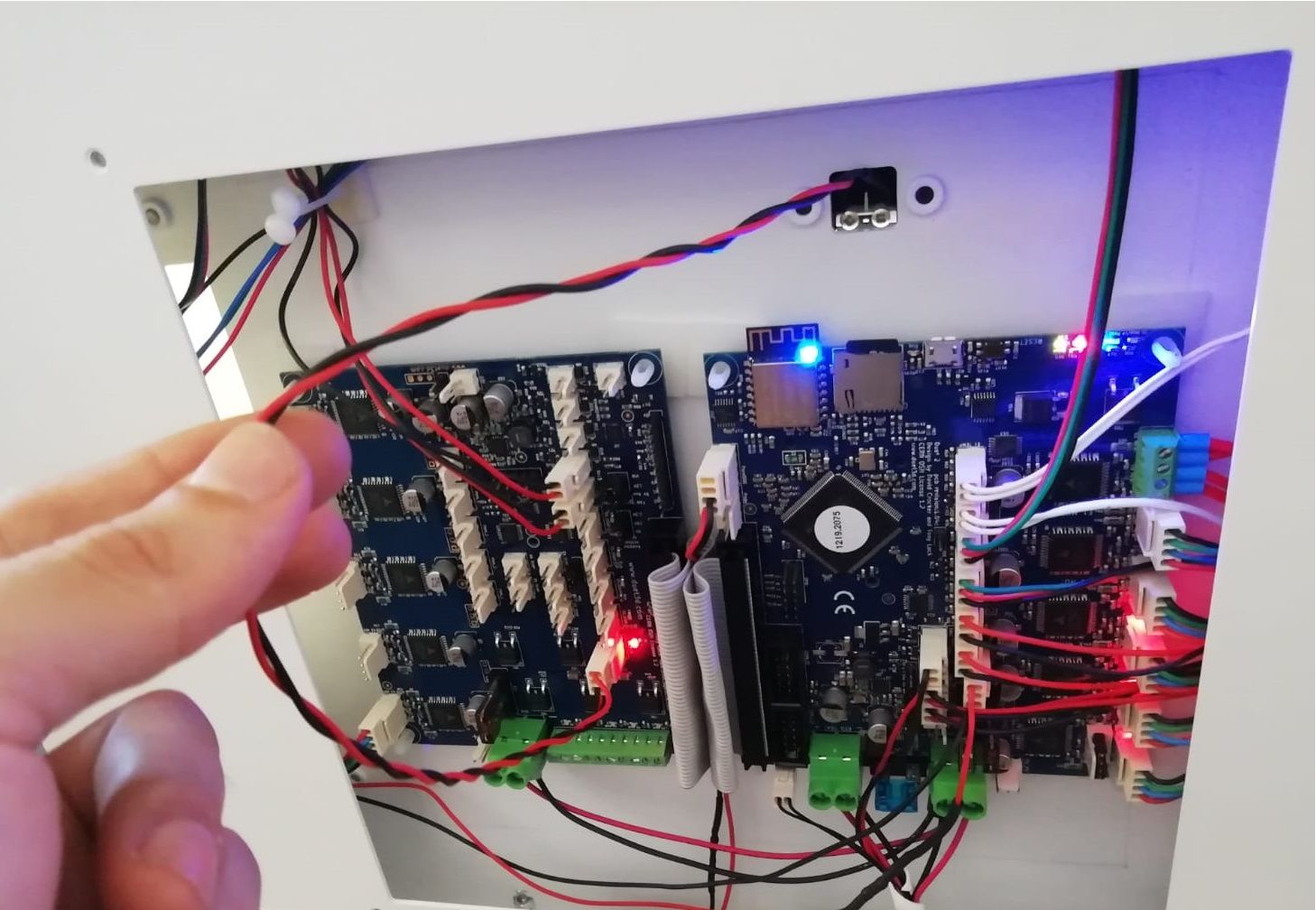
Is happening in different machines equally assembled. I attached you a picture to show you how I put the 2k resistor. Any idea of what is happening or how to solve it?I have seen in https://duet3d.dozuki.com/Wiki/Gcode#Section_M574_RepRapFirmware_Num_3:
P"pin_name" Defines the pin name(s) that the endstop(s) for the specified axis are connected to, see Pin Names. Needed when S=1. May need it ! before pin name to invert signal, or ^ to enable the pullup resistor, for example on the Duex expansion board.
M574 U2 S1 P"^duex.e2stop"Should I be using that way of the PIN output? If I do it, as soon as the machine touches the endstop, it gets blocked and does not recover until it stops touching the endstop. What is this for?
Thanks a lot again!
-
Can you try twisting the endstop wires?
-
Good morning,
I don't know what else to try, I've changed the endstop that was connected to the DUEX (U axis) and I put the Z endstop, but it still fails (Now, U axis that is in Duet 2 wifi, works well). This endstop is alone and is not near a motor wire. I tried to put it with a 2k resistor, also with the braided wires, but nothing, sometimes it does not detect it and others it thinks that it is always clicked (so the motor does not go to home position). Is a bit strange because the endstop is a normally closed sistem
Sometimes the limit switch doesn't detect it or it always does, the latter is the most common thing, which makes it stranger to me since it's a normally closed limit switch
What else can I try? Any suggestions?
Many thanks in advance
-
@Aitor I think your power wiring, both to the Duet and to the Duex, looks very thin. Is it of sufficient gauge to carry the current to supply the heaters, stepper motors and both Duet and Duex electronics? Also, you need a low resistance ground wire between the Duet and Duex to avoid crosstalk and the Duex using the ground wires in the ribbon cable for grounding (which may be causing your issue). So, ideally, use heavier gauge wiring on your power wiring, minimum 18AWG and preferably something bigger like 16 or 14AWG. Use the bootlace ferrules, too. See https://duet3d.dozuki.com/Wiki/Power_Wiring#Section_Main_power and https://duet3d.dozuki.com/Wiki/Duex2_and_Duex5_Features#Section_Wiring
Also, it looks like you wired the 2K resistor in line (is it under your fingers in the shrinkwrap in your earlier picture?) rather than between the endstop input and +3.3V.
Finally, it is not advisable to run wires near the Duet to Duex ribbon cable. The ribbon cable is unshielded, and can pick up interference.
Ian


