Pt100 sensor settings Problem
-
Hi everyone,
I have a Problem with the Pt 100 sensor settings.
When i connect the pt 100 sensor to the pt 100 daughterboard, the system shows my -273.1 degrees. When i connect the resistor to test it, it's the same. It shows -273.1 degrees.
Is there any wrong setting?
config.g file:
; Configuration file for Duet WiFi (firmware version 3)
; executed by the firmware on start-up
;
; generated by RepRapFirmware Configuration Tool v3.1.4 on Mon Aug 03 2020 15:55:28 GMT+0200 (Mitteleuropäische Sommerzeit)

; General preferences
G90                                                                  ; send absolute coordinates...
M83                                                                  ; ...but relative extruder moves
M550 P"Inno V1"                                                      ; set printer name
M575 P1 S1 B57600

; Network
M551 P"Inno3D"                                                       ; set password
M552 S1                                                              ; enable network
M586 P0 S1                                                           ; enable HTTP
M586 P1 S0                                                           ; disable FTP
M586 P2 S0                                                           ; disable Telnet

; Drives
M569 P0 S1                                                           ; physical drive 0 goes forwards
M569 P1 S1                                                           ; physical drive 1 goes forwards
M569 P2 S1                                                           ; physical drive 2 goes forwards
M569 P3 S1                                                           ; physical drive 3 goes forwards
M569 P4 S1                                                           ; physical drive 4 goes forwards
M569 P5 S1                                                           ; physical drive 5 goes forwards
M569 P6 S1                                                           ; physical drive 6 goes forwards
M569 P7 S1                                                           ; physical drive 7 goes forwards
M584 X0 Y1:4 Z2:5:6:7 E3                                             ; set drive mapping
M350 X16 Y16:16 Z16:16:16:16 E16 I1                                  ; configure microstepping with interpolation
M92 X800.00 Y883.20:883.20 Z883.20:883.20:883.20:883.20 E420.00      ; set steps per mm
M566 X900.00 Y900.00:900.00 Z12.00:12.00:12.00:12.00 E120.00         ; set maximum instantaneous speed changes (mm/min)
M203 X6000.00 Y6000.00:6000.00 Z180.00:180.00:180.00:180.00 E1200.00 ; set maximum speeds (mm/min)
M201 X500.00 Y500.00:500.00 Z20.00:20.00:20.00:20.00 E250.00         ; set accelerations (mm/s^2)
M906 X2000 Y2000:2000 Z2000:2000:2000:2000 E800 I30                  ; set motor currents (mA) and motor idle factor in per cent
M84 S30                                                              ; Set idle timeout

; Axis Limits
M208 X0 Y0 Z0 S1                                                     ; set axis minima
M208 X1500 Y2500 Z1500 S0                                            ; set axis maxima

; Endstops
M574 X1 S1 P"!xstop"                                                 ; configure active-high endstop for low end on X via pin !xstop
M574 Y2 S1 P"!ystop"                                                 ; configure active-high endstop for high end on Y via pin !ystop
M574 Z1 S2                                                           ; configure Z-probe endstop for low end on Z

; Z-Probe
M950 S0 C"duex.pwm2"                                                 ; create servo pin 0 for BLTouch
M558 P9 C"^zprobe.in" H5 F120 T6000                                  ; set Z probe type to bltouch and the dive height + speeds
G31 P500 X0 Y0 Z2.5                                                  ; set Z probe trigger value, offset and trigger height
M557 X15:1485 Y15:1485 S20                                           ; define mesh grid

; Heaters
M140 H-1                                                             ; disable heated bed (overrides default heater mapping)
M308 S0 P"spi.cs1" Y"rtd-max31865"                                   ; configure sensor 0 as thermocouple via CS pin spi.cs1
M950 H0 C"e0heat" T0                                                 ; create nozzle heater output on e0heat and map it to sensor 0
M307 H0 B0 S1.00                                                     ; disable bang-bang mode for heater  and set PWM limit

; Fans
M950 F0 C"fan0" Q500                                                 ; create fan 0 on pin fan0 and set its frequency
M106 P0 S0 H-1                                                       ; set fan 0 value. Thermostatic control is turned off

; Tools
M563 P0 D0 H1 F0                                                     ; define tool 0
G10 P0 X0 Y0 Z0                                                      ; set tool 0 axis offsets
G10 P0 R0 S0                                                         ; set initial tool 0 active and standby temperatures to 0C

; Custom settings are not defined

; Miscellaneous
M911 S21 R22 P"M913 X0 Y0 G91 M83 G1 Z3 E-5 F1000"                   ; set voltage thresholds and actions to run on power loss
Many thanks for your help!
-
@Inno-3D said in Pt100 sensor settings Problem:
M563 P0 D0 H1 F0 ; define tool 0
You have defined tool 0 to use heater 1 (H1), but you defined the heater earlier as H0. Change above line to:
M563 P0 D0 H0 F0 ; define tool 0
Ian
Bed-slinger - Mini5+ WiFi/1LC | RRP Fisher v1 - D2 WiFi | Polargraph - D2 WiFi | TronXY X5S - 6HC/Roto | CNC router - 6HC | Tractus3D T1250 - D2 Eth
-
@Inno-3D said in Pt100 sensor settings Problem:
M308 S0 P"spi.cs1" Y"rtd-max31865"
Also try spi.cs0 instead of cs1, assuming your PT100 sensor is connected to first port of daughterboard.
-
@aidar said in Pt100 sensor settings Problem:
Also try spi.cs0 instead of cs1, assuming your PT100 sensor is connected to first port of daughterboard.
I initially thought that too, but actually the pin names (listed here https://duet3d.dozuki.com/Wiki/RepRapFirmware_3_overview#Section_Pin_names_for_Duet_2_WiFi_Ethernet) are
spi.cs1
spi.cs2
spi.cs3
spi.cs4Ian
-
Also a pic of the daughter board wiring would maybe help as well
-
-
@Inno-3D said in Pt100 sensor settings Problem:
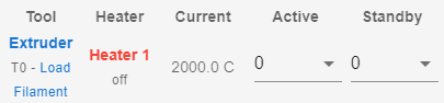
@droftarts Yes you are right now it shows 2000 degrees
@Dougal1957 here is a picture:

Remove the jumper and you need 2 that short the pairs together ie across pins 1&2 and 3&4
it needs to be the same as the other port on that board
-
@Inno-3D @Dougal1957 is correct, you need jumpers on all four pins if you're using a 2-wire PT100. See https://duet3d.dozuki.com/Wiki/Connecting_PT100_temperature_sensors#Section_To_connect_a_2_wire_PT100_sensor
Recent production PT100 daughter boards (v1.1 or later see the image above) have 2 sets of 2 jumper pins per channel. Install jumpers on those pins.
Ian
-
@Dougal1957 @droftarts Ah ok I've got it wrong.
Many thanks for your help!!
It's working now! -
@Inno-3D said in Pt100 sensor settings Problem:
@Dougal1957 @droftarts Ah ok I've got it wrong.
Many thanks for your help!!
It's working now!Glad you got it working.
You had effectively shorted the sensor which is why you got -273.1 an open gives you the 2000 reading (Normally)Doug
-
@Dougal1957 said in Pt100 sensor settings Problem:
You had effectively shorted the sensor which is why you got -273.1 an open gives you the 2000 reading (Normally)
It's the other way around: -273 means open circuit (ie nothing connected, infinite resistance), +2000 means short circuit (ie no resistance, because the jumper was on), because the resistance of a typical 100k thermistor decreases as it gets hotter. The PT100 and PT1000 are different, as the resistance increases as the temperature increases, but (I think) the chip on the daughter board inverts this and sends a reading to the Duet that works in the same direction as regular thermistors.
However, his initial -273 was because the tool was referring to a heater and temperature monitor that wasn't defined.
Ian
Bed-slinger - Mini5+ WiFi/1LC | RRP Fisher v1 - D2 WiFi | Polargraph - D2 WiFi | TronXY X5S - 6HC/Roto | CNC router - 6HC | Tractus3D T1250 - D2 Eth
-
@droftarts said in Pt100 sensor settings Problem:
@Dougal1957 said in Pt100 sensor settings Problem:
You had effectively shorted the sensor which is why you got -273.1 an open gives you the 2000 reading (Normally)
It's the other way around: -273 means open circuit (ie nothing connected, infinite resistance), +2000 means short circuit (ie no resistance, because the jumper was on), because the resistance of a typical 100k thermistor decreases as it gets hotter. The PT100 and PT1000 are different, as the resistance increases as the temperature increases, but (I think) the chip on the daughter board inverts this and sends a reading to the Duet that works in the same direction as regular thermistors.
However, his initial -273 was because the tool was referring to a heater and temperature monitor that wasn't defined.
Ian
Thanks for that Ian I din't know about the inversion in FW I did however know how the PT100 responds to changes in Temperature.
Doug