Stuck in spin loop, spinning module G-Codes
-
2-wire normally-open endstop switches connected to a DueX are most likely to pick up noise and cause a problem. 2-wire normally closed endstop switches and 3-wire endstop switches connected to DueX would only be likely to pick up noise if they run very close to stepper motor cables for some distance and the cables are not twisted pairs.
-
Hello @dc42,
The endstop that I still have in the duex is a two wire sensor, normally closed. But may be problem if wires go on a chain carrier with the wires of the motor (wires that are not braids), better if I put a 2k resistance to isolate the wires of the endstop?
Thanks again!
-
Hello @dc42,
In the tests that i have done this days, i have seen that the machine did not stop printing as before, but now we have the problem with the endstop that is connected to the duex, sometimes it does not work well:
Sometimes the machine thinks that is always pressed (the axis does not go to home position), others as if it was never pressed (so the motor hits against the endstop but nothing happens).
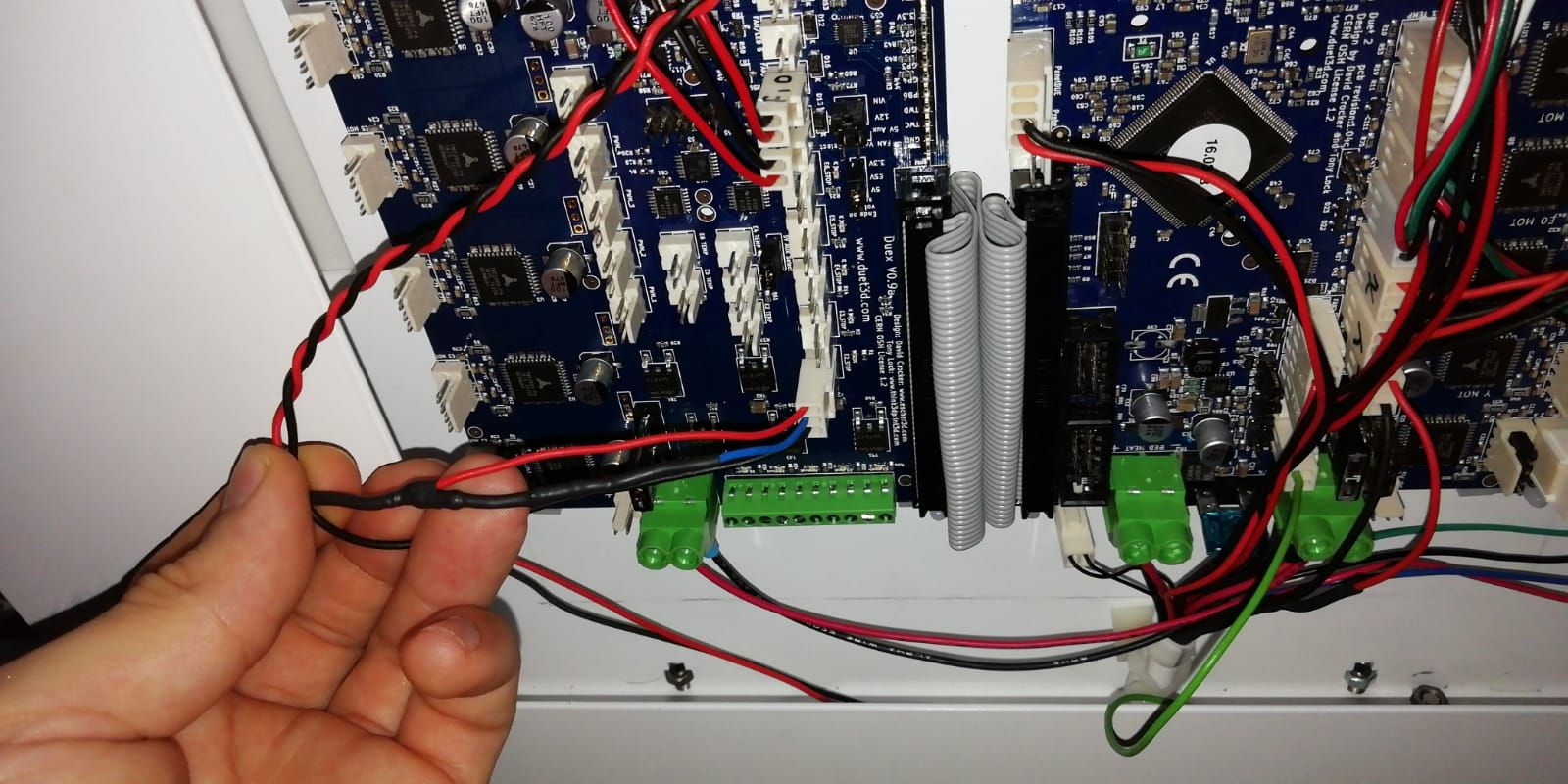
Is happening in different machines equally assembled. I attached you a picture to show you how I put the 2k resistor. Any idea of what is happening or how to solve it?
I have seen in https://duet3d.dozuki.com/Wiki/Gcode#Section_M574_RepRapFirmware_Num_3:
P"pin_name" Defines the pin name(s) that the endstop(s) for the specified axis are connected to, see Pin Names. Needed when S=1. May need it ! before pin name to invert signal, or ^ to enable the pullup resistor, for example on the Duex expansion board.
M574 U2 S1 P"^duex.e2stop"Should I be using that way of the PIN output? If I do it, as soon as the machine touches the endstop, it gets blocked and does not recover until it stops touching the endstop. What is this for?
Thanks a lot again!
-
Can you try twisting the endstop wires?
-
Good morning,
I don't know what else to try, I've changed the endstop that was connected to the DUEX (U axis) and I put the Z endstop, but it still fails (Now, U axis that is in Duet 2 wifi, works well). This endstop is alone and is not near a motor wire. I tried to put it with a 2k resistor, also with the braided wires, but nothing, sometimes it does not detect it and others it thinks that it is always clicked (so the motor does not go to home position). Is a bit strange because the endstop is a normally closed sistem

Sometimes the limit switch doesn't detect it or it always does, the latter is the most common thing, which makes it stranger to me since it's a normally closed limit switch
What else can I try? Any suggestions?
Many thanks in advance
-
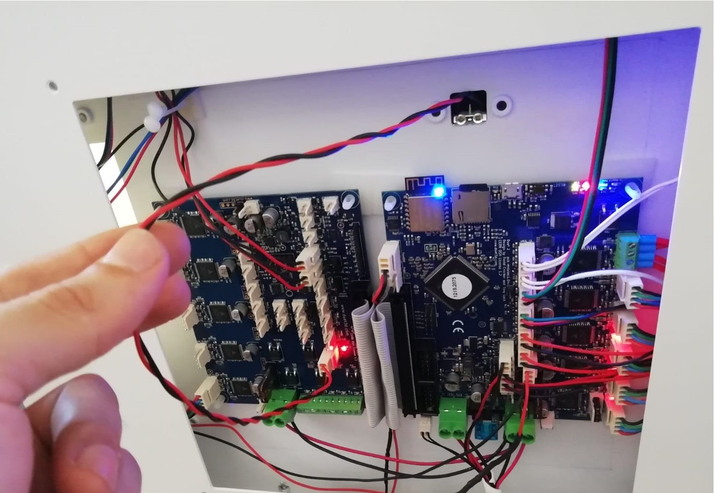
@Aitor I think your power wiring, both to the Duet and to the Duex, looks very thin. Is it of sufficient gauge to carry the current to supply the heaters, stepper motors and both Duet and Duex electronics? Also, you need a low resistance ground wire between the Duet and Duex to avoid crosstalk and the Duex using the ground wires in the ribbon cable for grounding (which may be causing your issue). So, ideally, use heavier gauge wiring on your power wiring, minimum 18AWG and preferably something bigger like 16 or 14AWG. Use the bootlace ferrules, too. See https://duet3d.dozuki.com/Wiki/Power_Wiring#Section_Main_power and https://duet3d.dozuki.com/Wiki/Duex2_and_Duex5_Features#Section_Wiring
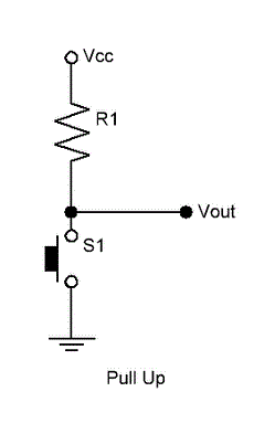
Also, it looks like you wired the 2K resistor in line (is it under your fingers in the shrinkwrap in your earlier picture?) rather than between the endstop input and +3.3V.
Finally, it is not advisable to run wires near the Duet to Duex ribbon cable. The ribbon cable is unshielded, and can pick up interference.
Ian
-
Hello @droftarts,
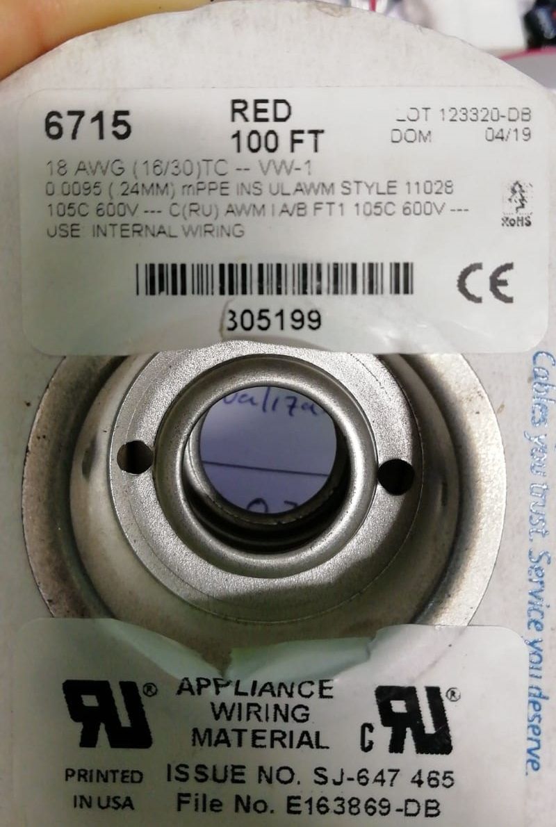
The wire that I am using to feed the motherboards is 18AWG with the splints on. I am going to order a 14AWG wire to test it (https://es.rs-online.com/web/p/conductores-de-interconexion-cables-para-equipos/6877607/)

How can I connect a ground wire between duet and duex? Can I use any free GND pin to connect them?
I have also tried to connect the ground I have in the chassis with a GND (green wire that you see in the image below connected to GND of always on fans) of the Duet 2 Wifi electronics, only in this one since I assume that the GND of both boards are connected, something that the polymeter tells me is correct, but this has not worked either
I have also removed the wire that was running through the flat wire in one of the machines, but others that didn't have it also fail. It doesn't matter what endstop I put in the duo that it will fail.
I have also tried to correct the pull up resistor connection, is it correct now?

With all this testing and changes, is still not working well, any other suggestion, idea or recommendation?
Many thanks in advance!
-
@Aitor said in Stuck in spin loop, spinning module G-Codes:
I tried to put it with a 2k resistor
To be clear, the 2K resistor should be connected between the STP and 3V3 pins of the endstop connector on the DueX. Is that what you did?
-
-
Hi,
This is how I connected power to my Duet WiFi/Duex 5 setups.
The two wires (red & black) connecting the two boards are SOLID 14 gauge.
The two wires from the middle of the of the two solid wires are STRANDED 14 gauge and go directly to the power supply. Spade lugs are crimped onto the ends of the wires connecting to the power supply.
The two stranded wires are soldered to the two solid wires.
The black substance you see where the stranded wires join the solid wires is "liquid electrical tape", a sticky, thick liquid that dries to a tough rubbery covering.
I've wired the Duet boards in all my printers using the approach and it has always proven to work.
Frederick

-
I am implementing a possible fix for this in RRF 3.2beta1, due out by the end of this week. I may be able to provide a firmware binary with the change before then.
-
@dc42 thank you so much. I will be eagerly waiting for the new beta RRF to test it.
Anyway, looking at the Duet, I have seen that I have the Zprobe signal free. Can I use it as an endstop and put there the endstop that I have in DUEX?
If it is possible, how should I connect and program it? -
@Aitor said in Stuck in spin loop, spinning module G-Codes:
How can I connect a ground wire between duet and duex? Can I use any free GND pin to connect them?
No, don't use a free ground pin. This may or may not be directly connected to the ground plane of the Duet PCB, so may or may not have sufficient copper trace to ground all current. As shown in the documentation https://duet3d.dozuki.com/Wiki/Duex2_and_Duex5_Features#Section_Wiring, use a short, thick wire from the VIN negative terminal of the Duet to the VIN negative terminal of the Duex.
I have also tried to connect the ground I have in the chassis with a GND (green wire that you see in the image below connected to GND of always on fans) of the Duet 2 Wifi electronics, only in this one since I assume that the GND of both boards are connected, something that the polymeter tells me is correct, but this has not worked either
Do you have a ground wire going from the frame to the negative terminal on your PSU? If not, you risk destroying your Duet if you do this. If you have a short circuit to the frame, it may short through the ground pin of the Duet. You should tie all grounds together, and to the negative on your PSU.
Once you have a ground wire from frame to PSU negative, it's also possible that you need to ground stepper motors to the frame. See https://duet3d.dozuki.com/Wiki/Choosing_and_connecting_stepper_motors#Section_Using_the_internal_drivers
It is highly recommended that the stepper motor casings be grounded, especially in belt-driven printers. Otherwise, motion of the belts causes static charge to build up, which eventually arcs over to the windings. Filament motion in extruders can cause static charge to build up on the extruder drive motor too. If the motors are screwed to a metal frame, grounding the frame is sufficient.
We generally recommend that you also connect mains ground to the V- output of your PSU. Check with the PSU manufacturer this is okay first, though. If you do this, watch out if you use a USB connection to the Duet, see the wiki page on USB ground loops. https://duet3d.dozuki.com/Wiki/USB_ground_loops
It's difficult to know where the issue is coming from. As it's the same across all your machines, it doesn't seem like it's the Duet or Duex. It does seem more like a wiring issue.
Ian
-
Hello @dc42
How´s the new firmware going?
I had "solved" my problem using the output "z probe" as an endstop for the U axis, including the 2k pullup resistance.
But I am eager to be able to test the new update that you told that maybe it will help aslo.Thanks a lot to all of you for helping me!
-
 undefined Triet referenced this topic
