Fans are lazy!
-
hey,
my fans are at 100%, but there are working with less power.
Before I had them on a chinese printer and the fan was much more powerful. How can I change this?; Configuration file for Duet 3 (firmware version 3) ; executed by the firmware on start-up ; ; generated by RepRapFirmware Configuration Tool v3.1.3 on Tue Jun 23 2020 22:36:44 GMT+0200 (Mitteleuropäische Sommerzeit) ; General preferences G90 ; send absolute coordinates... M83 ; ...but relative extruder moves M550 P"Duet 3" ; set printer name ; Drives M569 P0.0 S1 ; physical drive 0.0 goes forwards M569 P0.1 S1 ; physical drive 0.1 goes forwards M569 P0.2 S1 ; physical drive 0.2 goes forwards M569 P0.3 S1 ; physical drive 0.3 goes forwards M569 P0.4 S1 ; physical drive 0.4 goes forwards M569 P0.5 S1 ; physical drive 0.5 goes forwards M569 P1.0 S0 ; physical drive 1.0 goes forwards M569 P1.1 S1 ; physical drive 1.1 goes forwards M569 P1.2 S1 ; physical drive 1.2 goes forwards M584 X0.0 Y0.1 Z0.2:0.3:0.4:0.5 E1.0:1.1:1.2 ; set drive mapping M350 X16 Y16 Z16 E16:16:16:16:16:16 I1 ; configure microstepping with interpolation M92 X80.00 Y80.00 Z1600.00 E1600.00:1600.00:1600.00:92.70:92.70:92.70 ; set steps per mm ; set steps per mm M566 X900.00 Y900.00 Z12.00 E120.00:120.00:120.00:120.00:120.00:120.00 ; set maximum instantaneous speed changes (mm/min) M203 X6000.00 Y6000.00 Z180.00 E3600.00:3600.00:3600.00:1200.00:1200.00:1200.00 ; set maximum speeds (mm/min) M201 X500.00 Y500.00 Z40.00 E250.00:250.00:250.00:250.00:250.00:250.00 ; set accelerations (mm/s^2) M906 X1200 Y1200 Z3000 E3000:3000:3000:1200:1200:1200 I30 ; set motor currents (mA) and motor idle factor in per cent M84 S30 ; Set idle timeout ; Axis Limits M208 X0 Y0 Z0 S1 ; set axis minima M208 X700 Y700 Z800 S0 ; set axis maxima ; Endstops M574 X2 S1 P"!io3.in" ; configure active-high endstop for high end on X via pin !io3.in M574 Y2 S1 P"!io0.in" ; configure active-high endstop for high end on Y via pin !io0.in ; Z-Probe M558 P9 C"io4.in" H10 F200 T1800 ; set Z probe type to bltouch and the dive height + speeds M950 S0 C"io4.out" ; create servo pin 0 for BLTouch G31 P25 X-20 Y-20 Z2.5 ; set Z probe trigger value, offset and trigger height M557 X10:600 Y10:600 S200 ; define mesh grid ; Heaters M308 S0 P"temp0" Y"thermistor" T100000 B4138 ; configure sensor 0 as thermistor on pin temp0 M950 H0 C"out0" T0 ; create bed heater output on out0 and map it to sensor 0 M307 H1 S1.00 ; disable bang-bang mode for the bed heater and set PWM limit M140 H0 ; map heated bed to heater 0 M143 H0 S90 ; set temperature limit for heater 0 to 90C M308 S1 P"temp1" Y"thermistor" T100000 B4138 ; configure sensor 1 as thermistor on pin temp1 M950 H1 C"out1" T1 ; create nozzle heater output on out1 and map it to sensor 1 M307 H1 B0 S1.00 ; disable bang-bang mode for heater and set PWM limit ; Fans M950 F0 C"out3" Q500 ; create fan 0 on pin out3 and set its frequency M106 P0 S0.8 H-1 ; set fan 0 value. Thermostatic control is turned off M950 F1 C"out7" Q500 ; create fan 1 on pin out7 and set its frequency M106 P1 S1 H-1 ; set fan 1 value. Thermostatic control is turned off M950 F2 C"out8" Q500 ; create fan 2 on pin out8 and set its frequency M106 P2 S1 H T45 ; set fan 2 value. Thermostatic control is turned on ; Tools M563 P0 D0 H1 F0 ; define tool 0 G10 P0 X0 Y0 Z0 ; set tool 0 axis offsets G10 P0 R0 S0 ; set initial tool 0 active and standby temperatures to 0C ; Custom settings are not defined M671 X-19.5:99.5:99.5:-19.5 Y110:110:540:540 S2.5 ; Miscellaneous M501 ; load saved parameters from non-volatile memory M911 S10 R11 P"M913 X0 Y0 G91 M83 G1 Z3 E-5 F1000" ; set voltage thresholds and actions to run on powerKR
Richard -
Your fan0 is set to 80%
M950 F0 C"out3" Q500 ; create fan 0 on pin out3 and set its frequency
M106 P0 S0.8 H-1  ; set fan 0 value. Thermostatic control is turned off
If you want it full power at startup set it to S1.
-
@Phaedrux
hm ok... but fan on out3 has ´´S1´´ as parameter and it hasn´t that normal power. -
Is it a 12v or 24v fan?
You can try increasing the frequency of the fan PWM by changing the Q value in the M950 for that fan.
-
24v fan.. I´ll try to change the code.
Thanks, richard -
Looks like you are using a Duet 3. Have you set the fan voltage selection jumpers to the VIN position? Duet 3 is normally shipped with the jumpers in the 12V position.
Duet WiFi hardware designer and firmware engineer
Please do not ask me for Duet support via PM or email, use the forum
http://www.escher3d.com, https://miscsolutions.wordpress.com -
@dc42
yes. duet3.
I haven´t changed any jumpers.
So I can use 12v fans when using no jumpers?
Also on out3?
Because the fan on out 3 isn´t working at all.; Configuration file for Duet 3 (firmware version 3) ; executed by the firmware on start-up ; ; generated by RepRapFirmware Configuration Tool v3.1.3 on Tue Jun 23 2020 22:36:44 GMT+0200 (Mitteleuropäische Sommerzeit) ; General preferences G90 ; send absolute coordinates... M83 ; ...but relative extruder moves M550 P"Duet 3" ; set printer name ; Drives M569 P0.0 S1 ; physical drive 0.0 goes forwards M569 P0.1 S1 ; physical drive 0.1 goes forwards M569 P0.2 S1 ; physical drive 0.2 goes forwards M569 P0.3 S1 ; physical drive 0.3 goes forwards M569 P0.4 S1 ; physical drive 0.4 goes forwards M569 P0.5 S1 ; physical drive 0.5 goes forwards M569 P1.0 S0 ; physical drive 1.0 goes forwards M569 P1.1 S1 ; physical drive 1.1 goes forwards M569 P1.2 S1 ; physical drive 1.2 goes forwards M584 X0.0 Y0.1 Z0.2:0.3:0.4:0.5 E1.0:1.1:1.2 ; set drive mapping M350 X16 Y16 Z16 E16:16:16 I1 ; configure microstepping with interpolation M92 X80.00 Y80.00 Z1600.00 E92.70:92.70:92.70 ; set steps per mm ; set steps per mm M566 X900.00 Y900.00 Z12.00 E120.00:120.00:120.00 ; set maximum instantaneous speed changes (mm/min) M203 X6000.00 Y6000.00 Z180.00 E1200.00:1200.00:1200.00 ; set maximum speeds (mm/min) M201 X500.00 Y500.00 Z40.00 E250.00:250.00:250.00 ; set accelerations (mm/s^2) M906 X1200 Y1200 Z3000 E1200:1200:1200 I30 ; set motor currents (mA) and motor idle factor in per cent M84 S30 ; Set idle timeout ; Axis Limits M208 X0 Y0 Z0 S1 ; set axis minima M208 X700 Y700 Z800 S0 ; set axis maxima ; Endstops M574 X2 S1 P"!io3.in" ; configure active-high endstop for high end on X via pin !io3.in M574 Y2 S1 P"!io0.in" ; configure active-high endstop for high end on Y via pin !io0.in ; Z-Probe M558 P9 C"io4.in" H10 F200 T1800 ; set Z probe type to bltouch and the dive height + speeds M950 S0 C"io4.out" ; create servo pin 0 for BLTouch G31 P25 X-20 Y-20 Z2.5 ; set Z probe trigger value, offset and trigger height M557 X10:600 Y10:600 S200 ; define mesh grid ; Heaters M308 S0 P"temp0" Y"thermistor" T100000 B4138 ; configure sensor 0 as thermistor on pin temp0 M950 H0 C"out0" T0 ; create bed heater output on out0 and map it to sensor 0 M307 H1 S1.00 ; disable bang-bang mode for the bed heater and set PWM limit M140 H0 ; map heated bed to heater 0 M143 H0 S90 ; set temperature limit for heater 0 to 90C M308 S1 P"temp1" Y"thermistor" T100000 B4138 ; configure sensor 1 as thermistor on pin temp1 M950 H1 C"out1" T1 ; create nozzle heater output on out1 and map it to sensor 1 M307 H1 B0 S1.00 ; disable bang-bang mode for heater and set PWM limit ; Fans M950 F0 C"out3" Q500 ; create fan 0 on pin out3 and set its frequency M106 P0 S0.8 H-1 ; set fan 0 value. Thermostatic control is turned off M950 F1 C"out7" Q500 ; create fan 1 on pin out7 and set its frequency M106 P1 S1 H-1 ; set fan 1 value. Thermostatic control is turned off M950 F2 C"out8" Q500 ; create fan 2 on pin out8 and set its frequency M106 P2 S1 H T45 ; set fan 2 value. Thermostatic control is turned on ; Tools M563 P0 D0 H1 F0 ; define tool 0 G10 P0 X0 Y0 Z0 ; set tool 0 axis offsets G10 P0 R0 S0 ; set initial tool 0 active and standby temperatures to 0C ; Custom settings are not defined M671 X-19.5:99.5:99.5:-19.5 Y110:110:540:540 S2.5 ; Miscellaneous M501 ; load saved parameters from non-volatile memory M911 S10 R11 P"M913 X0 Y0 G91 M83 G1 Z3 E-5 F1000" ; set voltage thresholds and actions to run on power -
@dc42 How to switch the voltage with the jumpers?
Any explanation online?
thanks -
@barbarossa-cologne Docs can be found here.
-
@whosrdaddy
ok thanks.
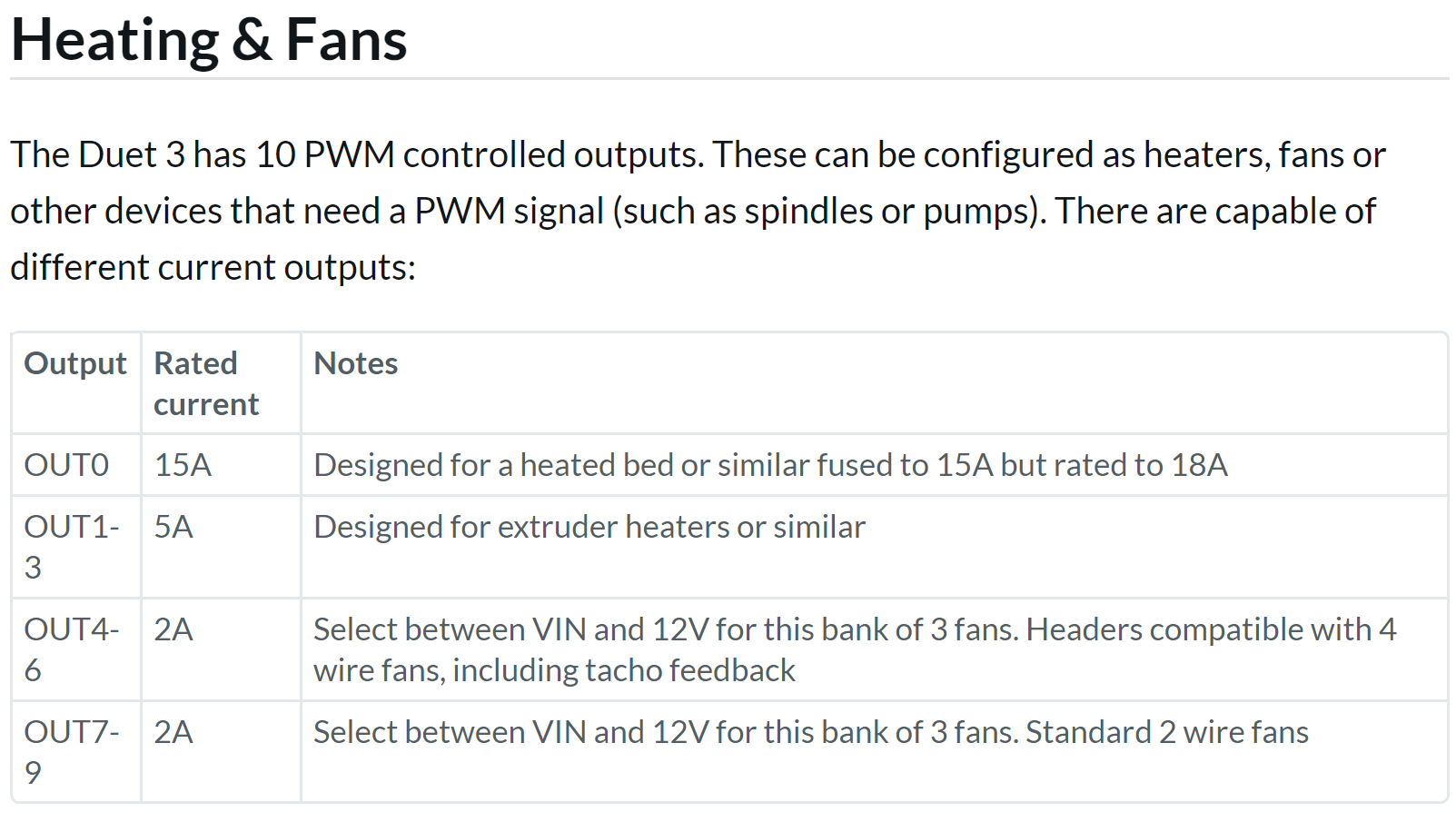
But shortly... is on out7 - out9 12v when I haven´t changed any jumpers?
KR
Richard -
@barbarossa-cologne : As DC42 said, standard the board is jumpered for 12V. If you read the link I gave you, you will find the following section (emphasis mine):
4-pin KK connectors with offset spigot OUT_4 thru OUT_6: these are intended for PWM-controllable fans. The connector fits a standard PC-type 4-pin PWM fan. Alternatively, a 2-pin fan may be connected between the V_OULCn pin (+ve) and the OUT_n_NEG pin (-ve). The positive supply to these connectors is the centre pin of the 3-pin jumper block labeled OUT4-OUT6_Select. A jumper in the top position will power them from the fused VIN supply. Alternatively you can connect a 3-terminal buck regulator to the 3-pin jumper block to supply the required voltage to the centre pin.
Seeing that you are using OUT7-OUT9, you must set the correspondend selection jumper to VIN, look at the hardware drawing at the link I gave you...
-
@whosrdaddy
Thanks...
This is maybe useful.....