Robotic kinematics
-
@JoergS5
ps . good morning! I re-read your help and I think I understand how it works (this feature)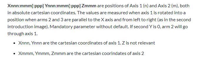
can you just tell me if there is a limit of coordinates x, y, z ? can this be put?
M669 K13 X70.0: 70.0 Y70.0: 70.0 Z50.0 ......... -
@tony73 you can simply build your robot as you like. You measure the properties of the robot after building the robot and set the parameters:
- measure arm lenghts 2 to 5
- measure where axis 1 and axis 2 are located and set parameters X, Y and Z according to the description (arms 2 and 3 parallel to x axis). Those coordinates are the places where you put the axes.
- measure and set the angles for all axes by homing or external measuring
Just build the robot, I will explain it better soon. From your questions I see that I did not explain it good enough. I will make it clearer with better images when I have a prototype my own and I can make images. The reason why I did not use images from the internet is, I wanted to avoid licensing problems.
-
good day! I saw that the updates continue! I found that if the size of the print bed (M208) is not right for the size of the robot arm, it won't move and write this (Error: G1 / G2 / G3: intermediate position outside machine limits). in (M208) should you put only X, Y, Z or also U, V?
Is parameter P1 working? can you give me an example how to change the angle of the 5th axis using P1?
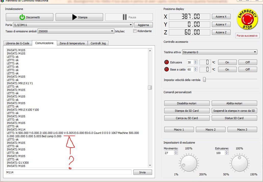
after homing the robot arm, before moving it, thinks it is stretched along the X axis with all the motors in 0 degree position (is that right or am I wrong?)another question, this is M114 immediately after homing, why does V always mark V 5.005? shouldn't it be zero? in M669 I put (P2: 0.0) thanks!
-
This post is deleted! -
This post is deleted! -
@tony73
I will finish the prototype next weekend and can then test the issues you have myself. I will tell you when I have fixed the source.If you want to lower the M208 limits to avoid your error, you could lower restrictions in the methods IsReachable and LimitPosition.
I will update the current status of development in the https://duet3d.dozuki.com/Wiki/Configuring_RepRapFirmware_for_a_FiveAxisRobot?revisionid=HEAD document near the begin of the document in the Status section. Here you can see that P1 is not supported yet.
-
@JoergS5 sounds like it’s nearly time to get my old Armdroid https://collection.sciencemuseumgroup.org.uk/objects/co470742/armdroid-robotic-arm-robotic-arm from the loft, dust it off, and install a Duet! Excited by this development, well done!
I did get it going with RAMPS, but only had four (of
sixfivesix (I forgot there are two for the wrist, that allows the gripper to either rotate around the wrist joint, or rotate in line with the wrist, which may be a challenge for kinematics)) motors working, and could only move the motors directly (no Kinematics).Ian
Bed-slinger - Mini5+ WiFi/1LC | RRP Fisher v1 - D2 WiFi | Polargraph - D2 WiFi | TronXY X5S - 6HC/Roto | CNC router - 6HC | Tractus3D T1250 - D2 Eth
-
@droftarts it would be great if you reactivate it!
The development is not finished yet and I have a lot of ideas in addition. But I want to have a good fundament first (firmware, documentation and hardware DIY description to help others to build a robot).
-
good morning! I did various tests, and I realized that I had to find the right relationship with lengths of the individual arms, min max angular limits of the joints and min max limits of (M208 in config.g)
I tried with these arms using 5 steppers i.e (R0) (L2 200mm L3 200mm L4 100mm L5 0mm) (X 0.0: 0.0 Y 0.0: 0.0 Z 100.0) or had to modify (from A-45: 45: 0: 75: - 75: -5: -170: 170: -135: 135 in A-45: 45: 0: 140: -140: -5: -170: 170: -135: 135) inside FiveAxisRobotKinematics.h I recompiled the firmware because I did not understand if I could modify them in M669, and I can tell you that with the parameters in equilibrium the motors move reaching more and more printing area.
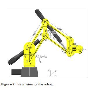
for the construction of the robot as you told me are you doing this?
-
@tony73 yes, I build it similar to this, but arm 4 longer down and axis 5 and arm 5 attached. The advantage is, that the arm 4 is vertical automatically and the upper and lower parallel arm elements will probably result in a higher precision (as the article described). I think it is similar like the parallel scara robot is more precise than a normal scara robot. I make the inner-arm-elements as wide and high as possible for the same reason, and axis 1 a big (30 cm diameter) plate.
The angle limits you mention can be set with the A parameter, although they are not reported yet. I will add them to the report. The report was so long, so I hesitated, but I compressed them now, so it's an advantage to get confirmation over all settings. It was a joy to use it in DWC while testing the parameters and changing all on-the-fly!
-
I would have
I wanted to build the same robot to be able to do the tests, but with my family, work and other things I have little time left, it would take too much to build, so I would have thought of this solution, I would buy this kit to shorten the time just mount it and connect the duet, it would be a thing in acceptable times !!
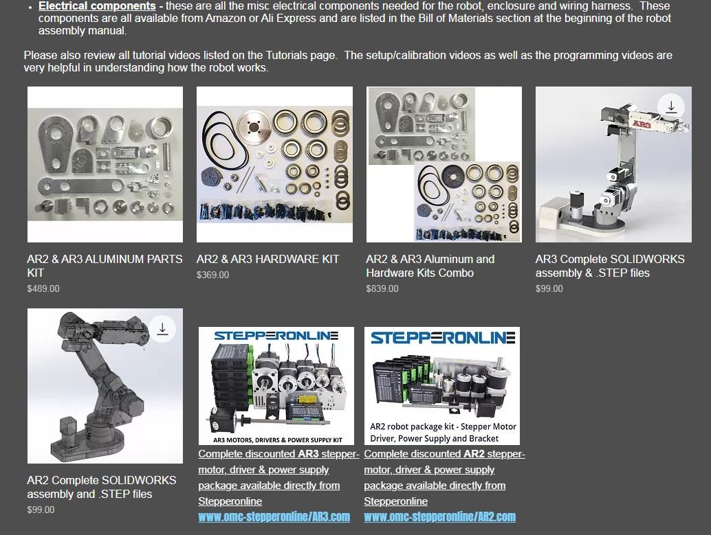
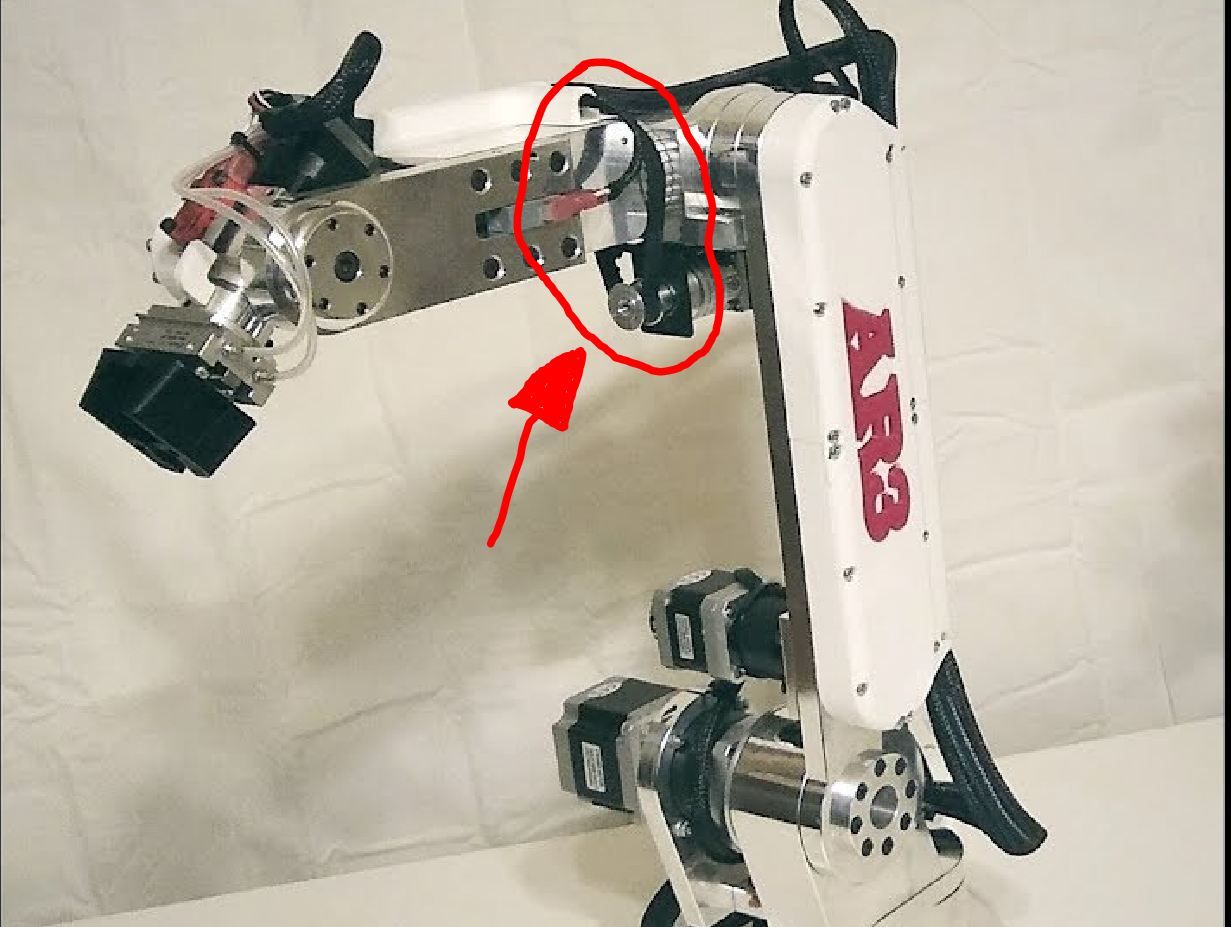
I would block the joint on arm 3 (L3) see photo !!! because this is a 6-axis and would be used as a 5-axis (a good compromise between price and quality, and in aluminum it should be stable in order to carry out acceptable tests!)
I hope that in the future you will be able to implement the 6th axis in the firmware, can you tell me if it will be possible or if this would complicate the firmware?
tell me if this robot seems like a valid solution to you !! Hello ! -
@tony73 before developing, I thought about whether to build this type of robot with the rotating 4th axis (6 in total), but I saw no advantage for a 3D printer, because the hotend holder shall be horizontal, the arm 4 vertical. And arm 5 long enough, so the extruder and other hotend parts can rotate freely around arm 4.
In the future the robot could be used for other tasks, CNC for example, where this flexibility would make sense. If I can master the kinematics/inverse kinematics task, I would like to develop this also. It is more complex of course.
Your robot offer has a relatively low gear ratio (my guess is 1:10 or even less). I suspect the precision is not good enough for 3D printing. But I have no experience, so it's only a guess.
I plan to develop and describe DIY building a robot as easy as possible in the reprap spirit (eg 3D print some of the printer parts*)) and describe it. It is an option for you to wait and decide whether it's better to build instead of buy. I understand your restrictions, but you have no project time deadline.
*) not the stiff parts of course!
-
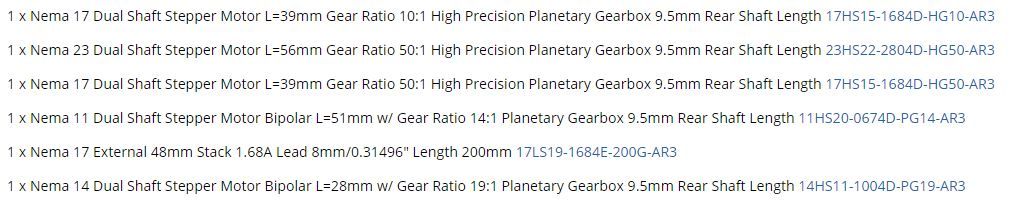
these are the motor reduction values that they describe, for you to see.
I was evaluating what I could do, I'm willing to wait even to see your robot and I don't know how many hours of work it takes but if they are reasonable I could follow you if you will release documentation to reproduce it, I have a lathe with modifications for manual cnc I could do the important pieces in aluminum.
I know that a 6 axis for 3d printing can be wasted, but as you said in the cnc field it is perfect, but let's go step by step! how much do you miss at the end of the robot? -
@tony73 said in Robotic kinematics:
I have a lathe with modifications for manual cnc I could do the important pieces in aluminum.
This will be sufficient. It would be an advantage to already have a 3D printer, but I have a plan to start without. I will release all what I am doing to build the robot.
-
I have a 3d printer I took it for granted !!some pieces for my scara are created with 3d printing !
-
@tony73 I only ask because I have an idea to use 3D printed gears, and one needs a printer already to create it. But I'll explain in a few days.
-
ok! I look forward to hearing from you !
-
@JoergS5
good morning ! how is work on the robot going on? -
@tony73 hello, my first try was too flexible, I am currently building version 2. You'll see it in a few days.
-
@JoergS5
OK, see you soon!