Robotic kinematics
-
I would have
I wanted to build the same robot to be able to do the tests, but with my family, work and other things I have little time left, it would take too much to build, so I would have thought of this solution, I would buy this kit to shorten the time just mount it and connect the duet, it would be a thing in acceptable times !!

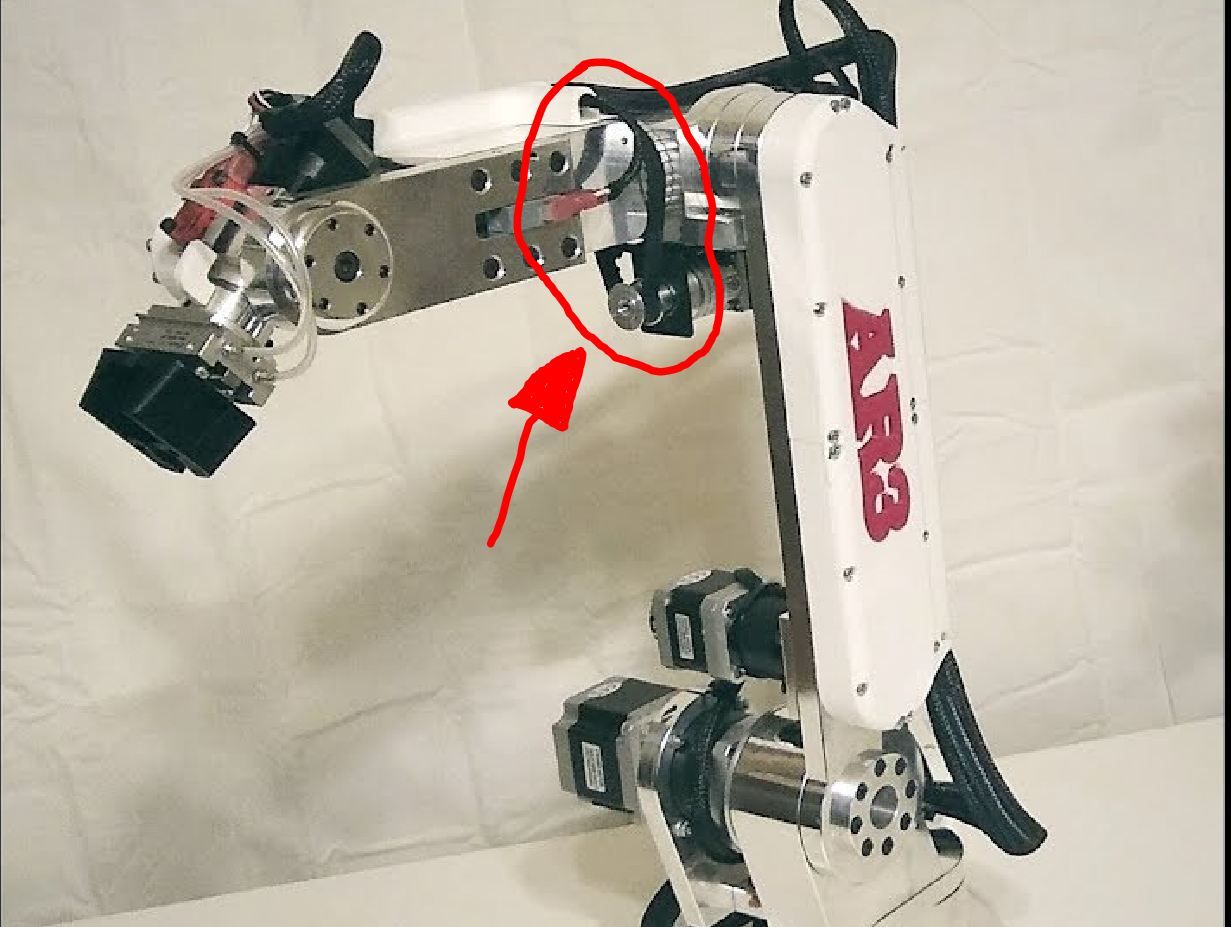
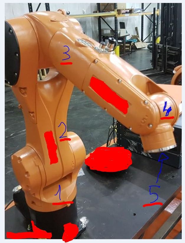
I would block the joint on arm 3 (L3) see photo !!! because this is a 6-axis and would be used as a 5-axis (a good compromise between price and quality, and in aluminum it should be stable in order to carry out acceptable tests!)
I hope that in the future you will be able to implement the 6th axis in the firmware, can you tell me if it will be possible or if this would complicate the firmware?
tell me if this robot seems like a valid solution to you !! Hello ! -
@tony73 before developing, I thought about whether to build this type of robot with the rotating 4th axis (6 in total), but I saw no advantage for a 3D printer, because the hotend holder shall be horizontal, the arm 4 vertical. And arm 5 long enough, so the extruder and other hotend parts can rotate freely around arm 4.
In the future the robot could be used for other tasks, CNC for example, where this flexibility would make sense. If I can master the kinematics/inverse kinematics task, I would like to develop this also. It is more complex of course.
Your robot offer has a relatively low gear ratio (my guess is 1:10 or even less). I suspect the precision is not good enough for 3D printing. But I have no experience, so it's only a guess.
I plan to develop and describe DIY building a robot as easy as possible in the reprap spirit (eg 3D print some of the printer parts*)) and describe it. It is an option for you to wait and decide whether it's better to build instead of buy. I understand your restrictions, but you have no project time deadline.
*) not the stiff parts of course!
-
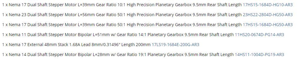
these are the motor reduction values that they describe, for you to see.
I was evaluating what I could do, I'm willing to wait even to see your robot and I don't know how many hours of work it takes but if they are reasonable I could follow you if you will release documentation to reproduce it, I have a lathe with modifications for manual cnc I could do the important pieces in aluminum.
I know that a 6 axis for 3d printing can be wasted, but as you said in the cnc field it is perfect, but let's go step by step! how much do you miss at the end of the robot? -
@tony73 said in Robotic kinematics:
I have a lathe with modifications for manual cnc I could do the important pieces in aluminum.
This will be sufficient. It would be an advantage to already have a 3D printer, but I have a plan to start without. I will release all what I am doing to build the robot.
-
I have a 3d printer I took it for granted !!some pieces for my scara are created with 3d printing !
-
@tony73 I only ask because I have an idea to use 3D printed gears, and one needs a printer already to create it. But I'll explain in a few days.
-
ok! I look forward to hearing from you !
-
@JoergS5
good morning ! how is work on the robot going on? -
@tony73 hello, my first try was too flexible, I am currently building version 2. You'll see it in a few days.
-
@JoergS5
OK, see you soon! -
This post is deleted! -
@dc42 I have two short questions and hope you can easily answer them:
The M208 XYZ, are they cartesian coordinates, and when using U it is meant as a second X? For rotational actuators, I would use the result of the kinematics world coordinates for the M208 values, not the angles? Do I understand this correctly?
I have to inform the kinematics in advance before the G0/G1 move starts, what the complete movement will be. I added a seperate method for this in the kinematics. Where shall I add the call? (DDA/Move/...Init/Spin?) and are there additional parts where I have to add it (mesh compensation eg).
-
It's entirely up to you what you use the U axis for. In the CNC world, conventionally UVW behave like a second XYZ system, and ABC are rotational axes. But RRF doesn't require that.
Duet WiFi hardware designer and firmware engineer
Please do not ask me for Duet support via PM or email, use the forum
http://www.escher3d.com, https://miscsolutions.wordpress.com -
@dc42 I meant are M208 values cartesian coordinates or stepper positions?
-
@JoergS5 said in Robotic kinematics:
@dc42 I meant are M208 values cartesian coordinates or stepper positions?
They are in whatever units your kinematics assumes for U parameters in G1 commands.
Duet WiFi hardware designer and firmware engineer
Please do not ask me for Duet support via PM or email, use the forum
http://www.escher3d.com, https://miscsolutions.wordpress.com -
@dc42 ok thanks, I try to use it correctly.
-
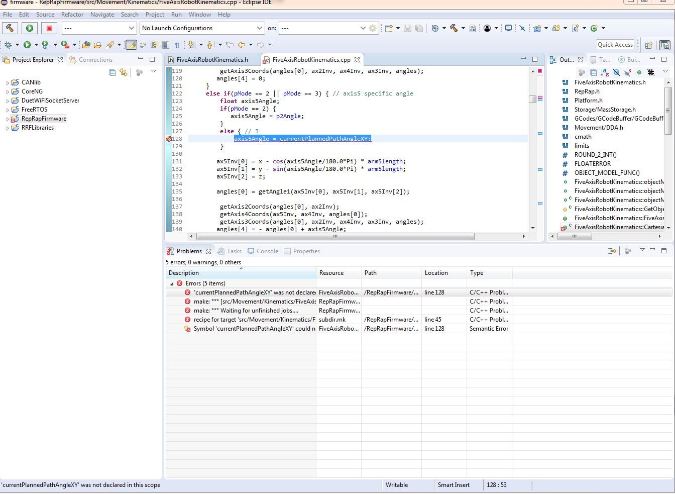
good morning ! I took the two files with the latest changes FiveAxisRobotKinematics.h and FiveAxisRobotKinematics.cpp I put them in rrf 3.1.0 as I always did, I tried to in eclipse to recompile the .bin gives me this error,
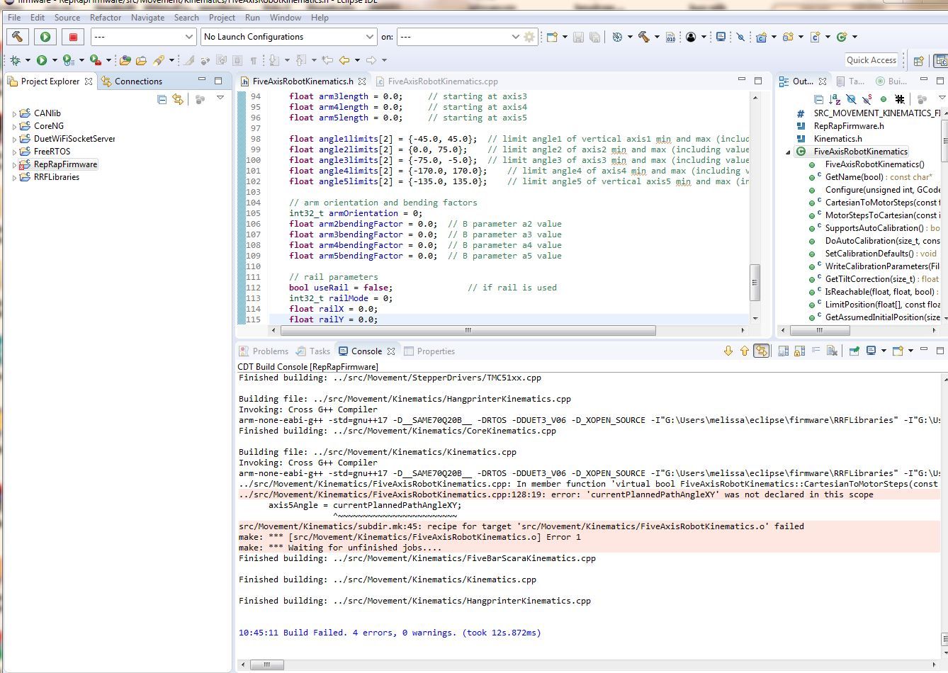
could you help me ? I don't know where I'm wrong!
-
@tony73 you're right, I missed checking it in into github. I'll do this in a minute. The variables are a prepration to support P3 (hotend in the direction of the movement) and a new P4.
Sorry that I overlooked it.
-
OK! eclipse firmware reloaded works! I would like to start building a robot that looks like this
with example link 1 /150mm, link 2/ 200mm, link 3/ 200mm, link 4/ 100mm, link 5/ 80mm
the (link 4 could be 100mm? considering that I don't know if link 2 can go to less than 0 degrees (type arm 2 max 75 degrees min -45 degrees? and could you say reduction ratio would serve on the basis of these arms, for the 5 engines?maybe I made a wrong speech!
if link 1 is 150mm, I can make link 4 of 100mm that is 50mm less than link 1, can there be a problem or can it be done? can create problems at link 2 for min angle 0? -
@tony73 I think you confuse some of the distances, What you mark as link 1 distance has no meaning. Only how much it can rotate is important.
=> to answer your question, different axis lengths are no problem. Longer will probebly be more stable. I will use between 100 and 200 also.Link 2 min angle 0 is no problem. You must calibrate the angle at a different angle (eg 90 degree).
Your question according reduction ratio: which ratio do you plan?
At the 5 you must assemble something horizontal to hold a hotend if you want to use it for 3d printing.
The robot as such looks very stiff and will be precise (if the ratio is ok) imho. In axis 5 could be a harmonic drive. A planetoid gear could have backlash, but you could run it in P0 mode.Axis 1 is very important to be precise (exactly horizontal rotation eg), you should consider making the rotating plate as big/good/stiff as possible.