Can Duet3D boards drive Cool Muscle closed-loop motors?
-
Hello, could not decide which subforum this should go in, so posting here.
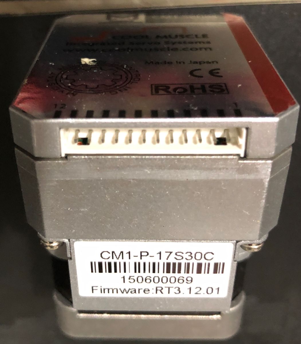
I have a 5 extruder printer from a now-defunct Canadian company. As I was a neophyte when I bought it I was oversold and ended up upgrading to 7 high-end closed-loop motors.
I never used 4 of the extruders and now I seem to be having problems with the proprietary mainboard.
I am contemplating moving to a new motherboard and selling off the extra 4 motors or selling off the whole printer to someone with more technical expertise than I have.
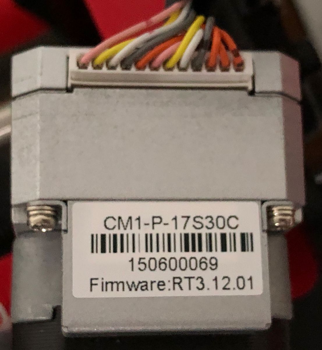
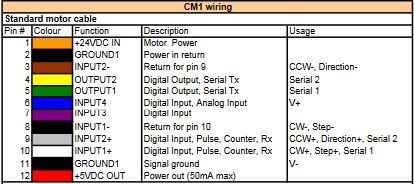
My question is - can the Duet boards drive the closed-loop motors? they have 12 pin connectors.
Is it just a different cable that is required (and some FW updating)?
The site for the motors claims that you can control the motors off a USB and a laptop so I do not understand the need for the 12 wires. Perhaps they are a generic connector that allows for added control?
Any help/tips/advice is appreciated.
Thanks,
M./
-
It looks like they are using the pololu type sockets... if that's correct they may will work in an board that uses that pinout. No reason you couldn't setup something to do the same with a duet.
You really want the datasheet/pinout for the motors to be sure, and the manufacturer wants you to register or something.
-
Thanks much for the reply.
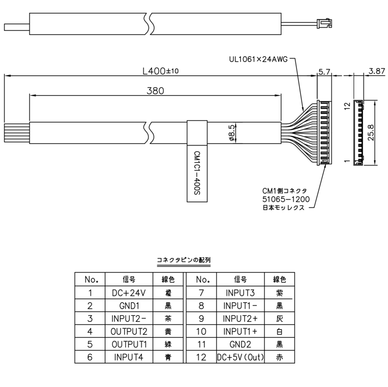
I did find a drawing in their support area for a model is the same series as I have.
Mine are 17C and the drawing is for 17E but I would have to think they would not change the pinouts, just have improvements internally.
So, if I use the right pins, I might be able to use the motors on a printer with a board with the normal 4 or 5 pin connectors?
Also, is there a forum that someone could recommend for listing the printer or the motors for sale?
The units are fairly specialized so Craigslist doesn’t seem like it would be the right venue.
Again, thanks for the advice.
M./
-
@Motolectric said in Can Duet3D boards drive Cool Muscle closed-loop motors?:
Thanks much for the reply.
I did find a drawing in their support area for a model is the same series as I have.
Mine are 17C and the drawing is for 17E but I would have to think they would not change the pinouts, just have improvements internally.
That's a big assumption. They could be different models completely.
So, if I use the right pins, I might be able to use the motors on a printer with a board with the normal 4 or 5 pin connectors?
No.
The 4 pin connection is intended to directly drive a motor.
To control these motors from a duet would mean bypassing the existing drivers on the board. Instead you are sending step and direction commands (I assume).
So you would need to know what those input/output pins actually do. -
@Motolectric said in Can Duet3D boards drive Cool Muscle closed-loop motors?:
I would assume INPUT# + and - are the differential pairs, most high end drivers take differential input .. so most probbly you have here
INPUT1 and 2 + - is probably step or direction
INPUT3 and 4 is probably enable or serial RX (this one is not differential so I assume slow signal)
OUTPUT1 and 2 are probably serial TX and interrupt/error/all-ok
simple logic analyzer should confirm what pin does with by monitoring initialization and few moves.
also that board with those sockets and 4 pin outputs over them really looks like designed for pololu style drivers so reverse engineering that small board should be super simple to see what pin on the pololu header goes to what pin on the motor driver

I doubt duet knows how to talk to these drivers so you would not be able to configure them from RRF, just drive them "as is" using en/dir/step signals that you can get from the Duet Expansion Breakout Board (you have output for 5 steppers there)
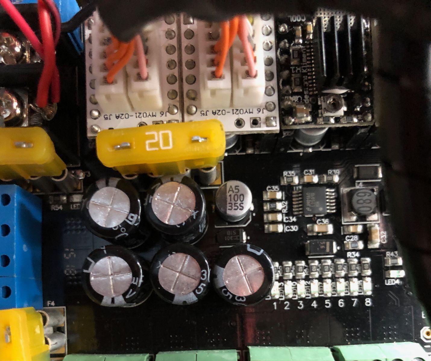
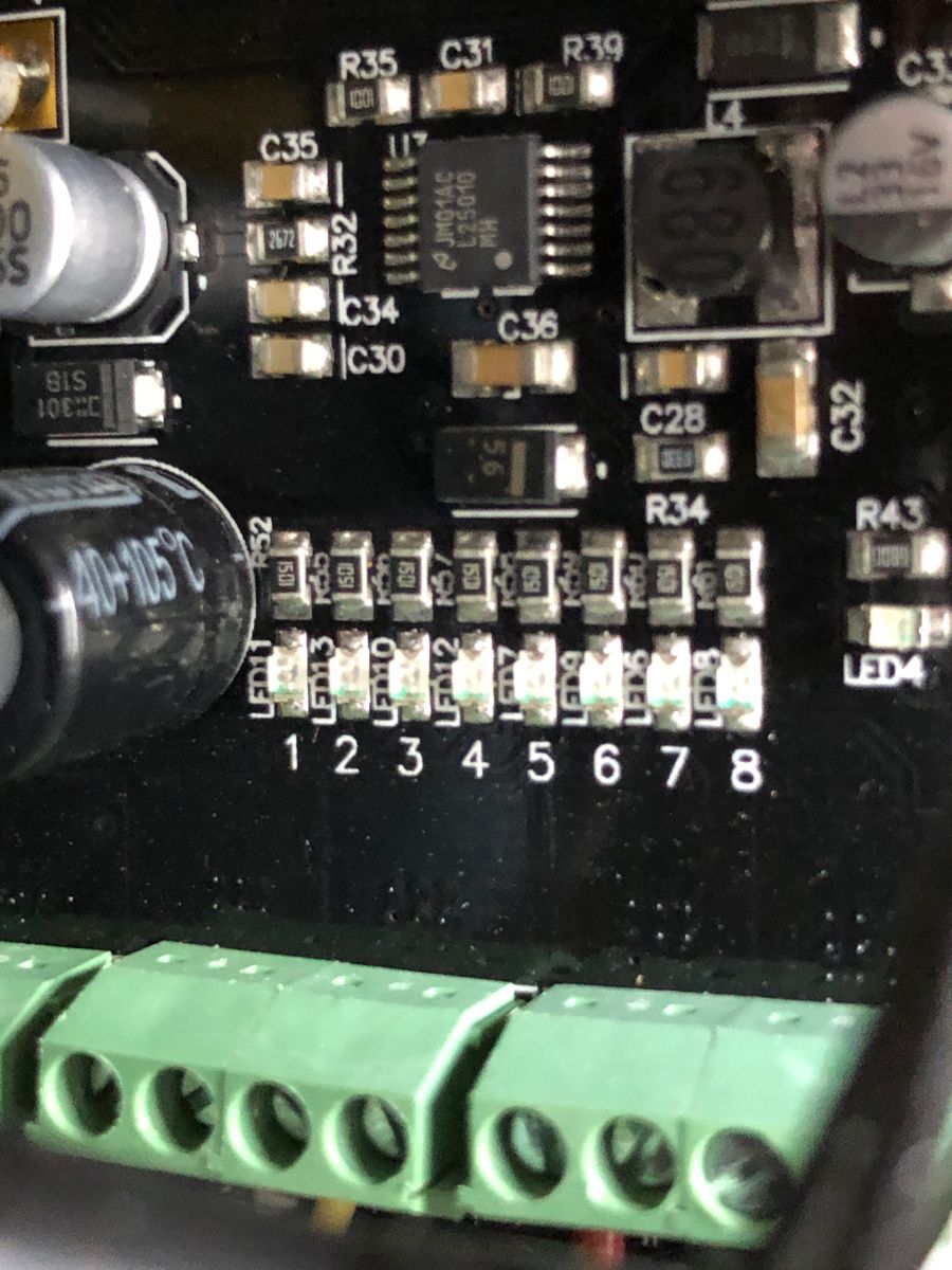
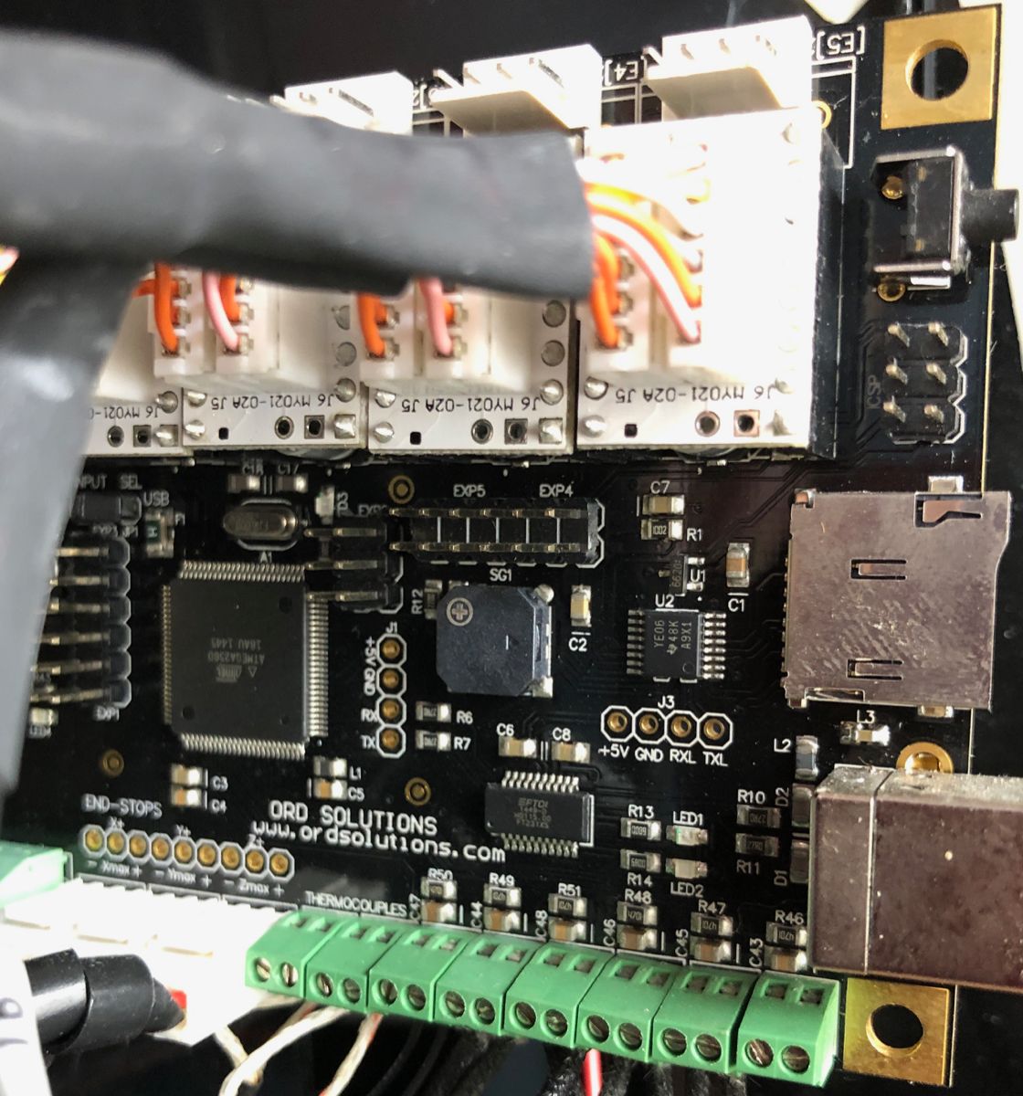
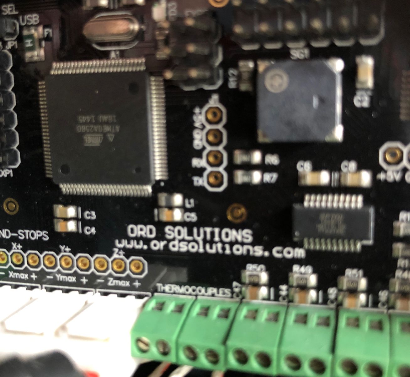
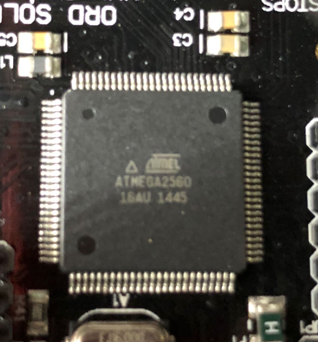
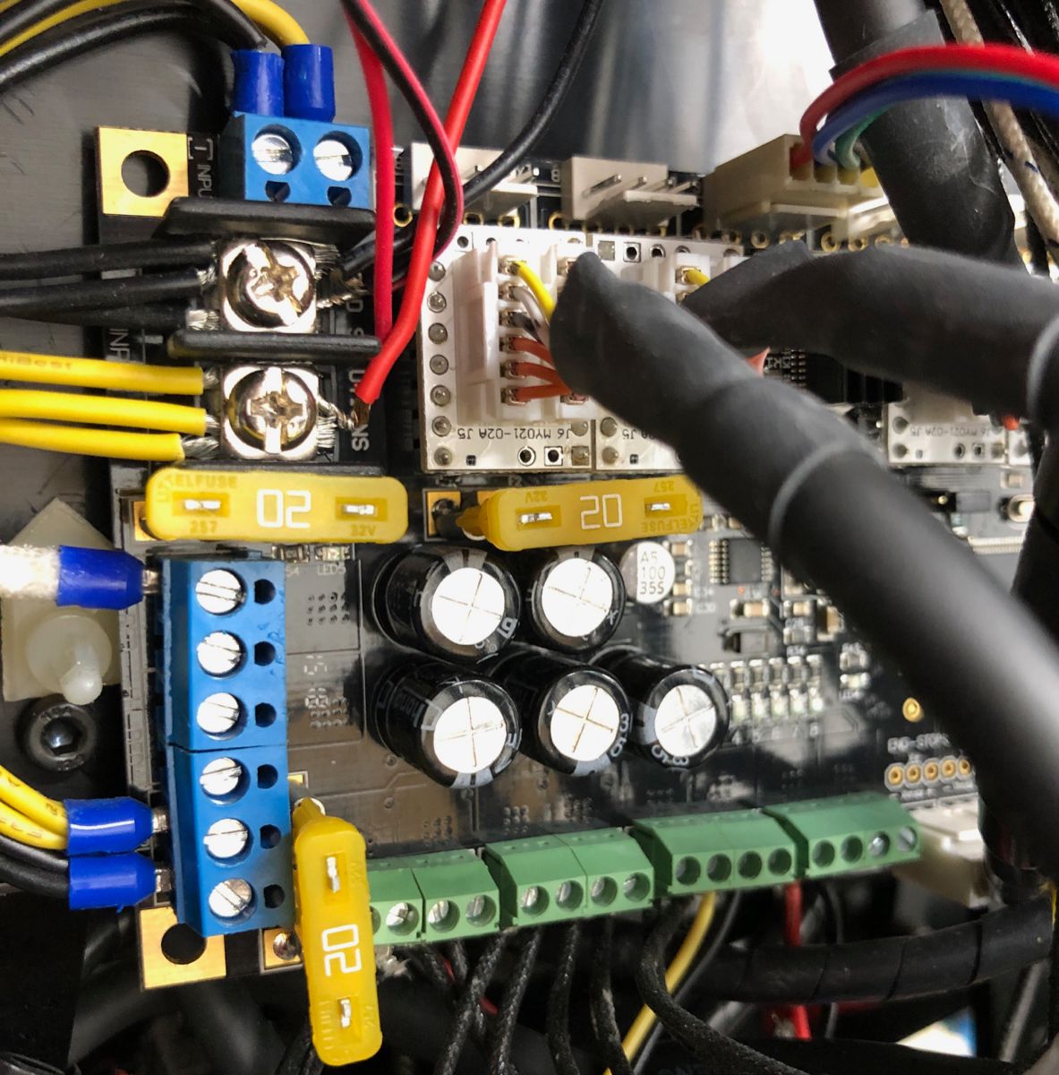
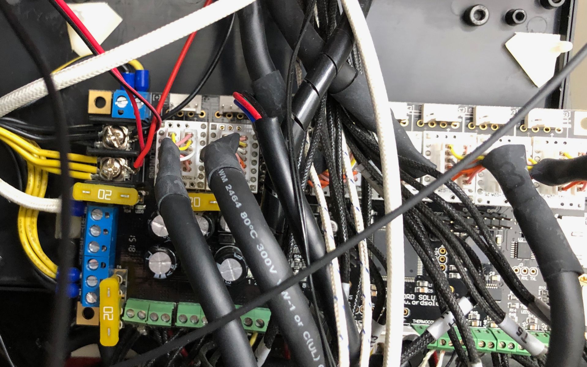
anyhow, that "proprietary board", often those are just clones of something existing, rarely they are designed from scratch. Take a few good pictures of the both side of the board so we can see major chips there and probably will someone recognise what board it is or at least what it is based on...
-
Thanks for the advice. He may have just had his name screened onto a generic board. I will follow up with the motor maker to see if they will give me some info since I own 7 of them. I remember that the upgrade for the 7 motors was about $2K.
The part of this discussion that confused me was that the current trend towards adding on the little closed-loop circuits to the back of the motors still used the standard cable from the boards. So it seemed to me that all of the upgrading needed to offer the closed-loop performance was in the add-on circuit and that perhaps all of that was just housed in the Cool Muscle motors.
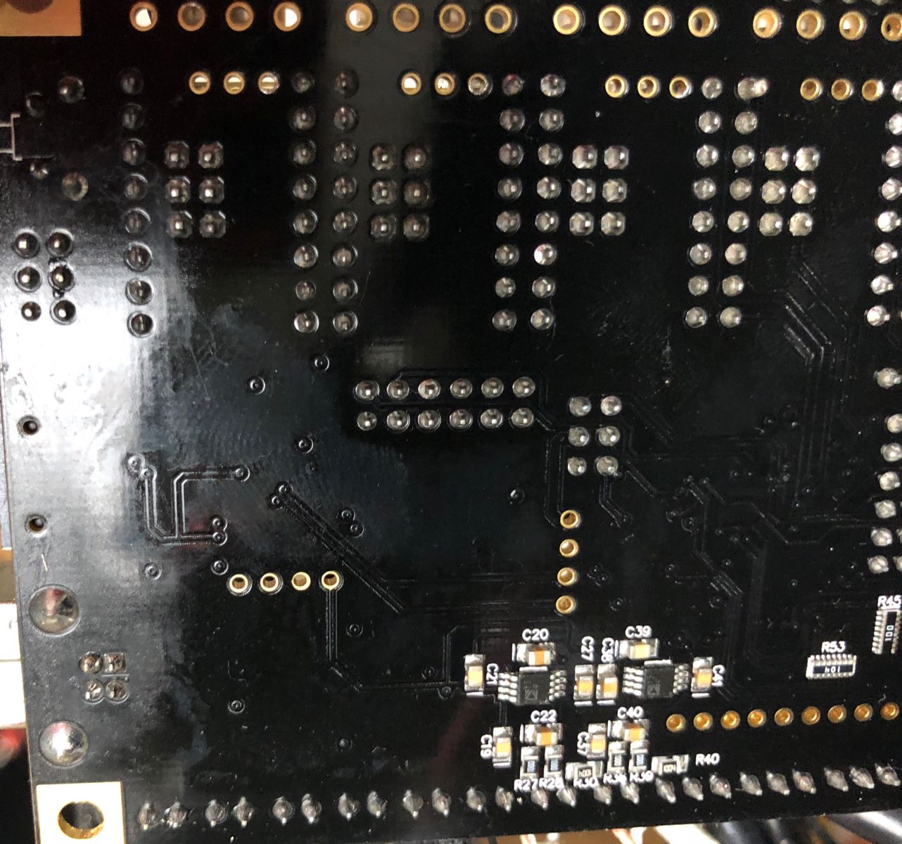
Here are some photos of the board.
Any and all help is much appreciated.
Thanks,
M./
-
-
board does not look familiar to me but someone might recognise it.
if you remove one of the white daugterboards that look like pololu headers is there anything on the silkscreen? any marking around the headers?
do you remember how was this printer working without closed loop drivers, do you know how "normal" drivers looked like?
without sampling the signal or datasheet from the manufacturer everything is gueswork at this point
-
Seems like the manuals and specs are here
-
Thanks, man, I don't know why I did not find that outfit in my searches.
And since they are a Canadian business I know they are the ones that supplied the printer maker.
Based on reading their docs ( a little) I think my original supposition might be correct,
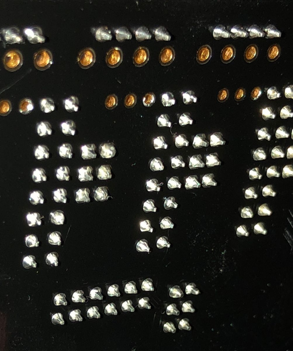
that (in this implementation) the closed-loop motors are a drop-in upgrade and the 12 pin connectors are just being used as the easiest way to interface with them. I had hoped that a photo would let me see if only some of the traces linked up to the connector interface cards but I can't see (photo below).
Since this started as a Kickstarter campaign I'm pretty sure they were doing things as cheaply as possible.
And buying premade cabling and some motherboard connectors would be the cheapest way to go vs. making up custom cables that only connected the pins that were actually used.As I mentioned prior, the ability to add a closed-loop daughter card to the back of a stepper motor and then update a few parameters and have it be driven by the existing motherboard leads me to believe that the added capability is in the daughtercard board and in the case of the Cool Muscle motor it's just internal.
And they did not have different firmware files for whether you had the original stepper motors or the CM.
I think any updating/tweaking was only done through the terminal.
But I will check with the Canadian distributor to see what they say.
Thanks again for the very useful link.
M./
-
That right there is an Azteeg X3 Pro. https://www.panucatt.com/Azteeg_X3_Pro_p/ax3pro.htm
Specifically, it is a clone of an Azteeg X3 Pro. The genuine boards have screw terminals where the clones have Molex 4-pin headers.
As others said, the expansion board should work but it is difficult to say what sort of cost/benefit ratio you would be looking at versus getting a replacement Azteeg and trying to figure out the firmware.
