Trouble with first test print
-
-
Your should remove the M375 from the config. you need to establish z=0 before you load the height map.
also its a good idea to remove the M302 P0 from the config and only issue it when its required.
you have a big printer. your steps per mm are rather uncommon. 300 and 350.
you have configured a z endstop and a probe. is that really what you want?
can you post the beginning of the g code you are trying to print?
-
also your probe has an offset of 24cm?
and why does your tool have an offset of 24cm?
tool 0 should have no offset
-
Ah, I see what you mean. So the steps per mm are too low? I used the values from the axis position on the duet web control to calculate the distance from the z probe to the nozzle offset. I think that’s what you mean by the steps per mm are odd, they are off the actual print area is about 800mm by 800mm. To calibrate the axis should I measure the distance the axis travels from a point and adjust the steps accordingly similar to calibrating the feed rate or e steps? Thanks.
-
@1997alex said in Trouble with first test print:
To calibrate the axis should I measure the distance the axis travels from a point and adjust the steps accordingly similar to calibrating the feed rate or e steps?
That's one way to do it, but you can usually get a pretty accurate mathmattical estimate based on the physical properties of your parts. But I'm not sure if you're using regular 3d printing hardware here.
Can you give us some more details about your printer? It's very large.
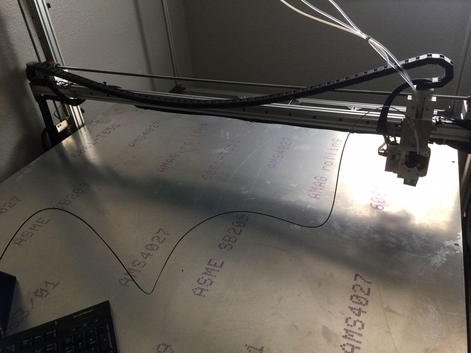
You say the print area is 1800x1800 but your axis maxima is much larger. Can you post a photo of it?
You might be able to post your gcode files now. So please try and share the file you're trying to print. Also include your homing files and config.g as text. Makes it a lot easier than a photo.
-
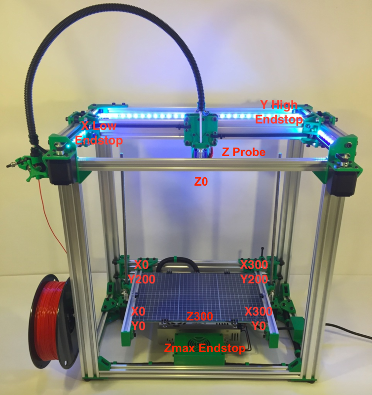
Here is my code and the actual printing area is around 800mm x 800mm, I was using the values from the duet web control to find the printing areas max and min which were wrong at first. That's why the axis max and min values were so high (3400 x 4900) and e steps were way to low and thankfully I fixed it and now its a lot more accurate than before. As for the actual parts used on my printer, they are 1000mm linear rails and 1200mm lead screw for each axis. a few pf the parts on the printer are cut aluminium used a caliper to measure everything. I'm using aluminium extrusion for the frame and supports all around which were purchased from misumi. Heres a photo of the printer, it needs alot of work still and its in my office with limited space so I couldnt get a wider shot and I figure this would give you an idea of what it looks like. Thanks again for all the help.
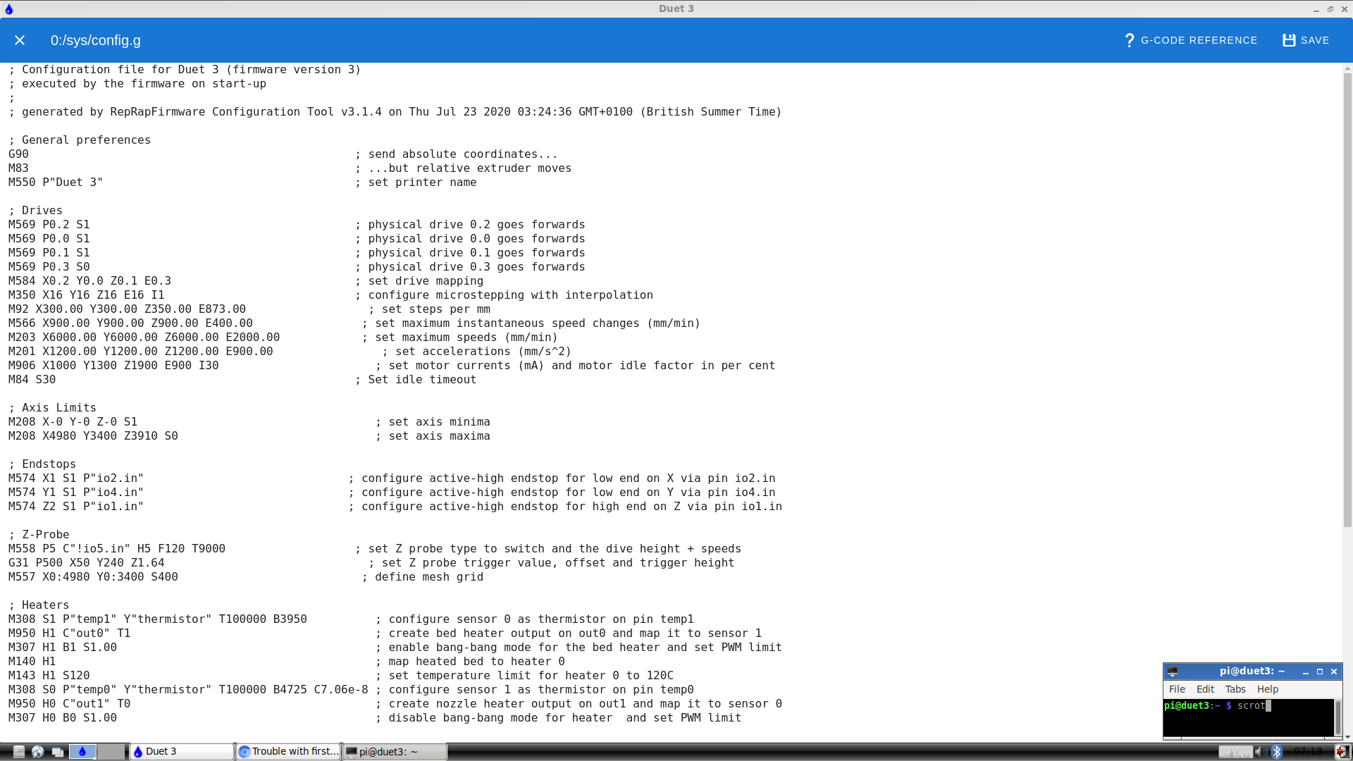
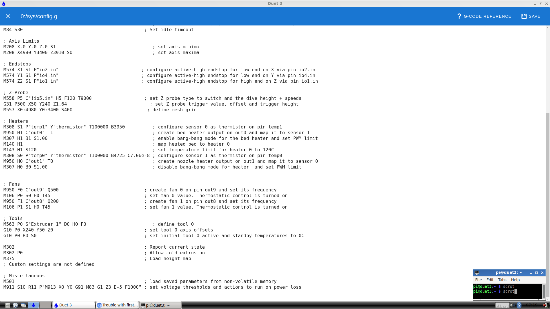
; General preferences G90 ; send absolute coordinates... M83 ; ...but relative extruder moves M550 P"Duet 3" ; set printer name ; Drives M569 P0.2 S1 ; physical drive 0.2 goes forwards M569 P0.0 S1 ; physical drive 0.0 goes forwards M569 P0.1 S1 ; physical drive 0.1 goes forwards M569 P0.3 S0 ; physical drive 0.3 goes forwards M584 X0.2 Y0.0 Z0.1 E0.3 ; set drive mapping M350 X16 Y16 Z16 E16 I1 ; configure microstepping with interpolation M92 X1615.00 Y1615.00 Z1608.00 E873.00 ; set steps per mm M566 X300.00 Y300.00 Z300.00 E400.00 ; set maximum instantaneous speed changes (mm/min) M203 X950.00 Y950.00 Z950 950.00 ; set maximum speeds (mm/min) M201 X300.00 Y300.00 Z300.00 E400.00 ; set accelerations (mm/s^2) M906 X1500 Y1800 Z1800 E900 I30 ; set motor currents (mA) and motor idle factor in per cent M84 S30 ; Set idle timeout ; Axis Limits M208 X-0 Y-0 Z-0 S1 ; set axis minima M208 X900 Y700 Z849.47 S0 ; set axis maxima ; Endstops M574 X1 S1 P"io2.in" ; configure active-high endstop for low end on X via pin io2.in M574 Y1 S1 P"io4.in" ; configure active-high endstop for low end on Y via pin io4.in M574 Z2 S1 P"io1.in" ; configure active-high endstop for high end on Z via pin io1.in ; Z-Probe M558 P5 C"!io5.in" H5 F120 T9000 ; set Z probe type to switch and the dive height + speeds G31 P500 X45 Y40 Z0.15 ; set Z probe trigger value, offset and trigger height M557 X0:900 Y0:700 S40 ; define mesh grid ; Heaters ;M308 S1 P"temp1" Y"thermistor" T100000 B3950 ; configure sensor 0 as thermistor on pin temp1 ;M950 H1 C"out0" T1 ; create bed heater output on out0 and map it to sensor 1 ;M307 H1 B1 S1.00 ; enable bang-bang mode for the bed heater and set PWM limit ;M140 H1 ; map heated bed to heater 0 ;M143 H1 S120 ; set temperature limit for heater 0 to 120C M308 S0 P"temp0" Y"thermistor" T100000 B4725 C7.06e-8 ; configure sensor 1 as thermistor on pin temp0 M950 H0 C"out1" T0 ; create nozzle heater output on out1 and map it to sensor 0 M307 H0 B0 S1.00 ; disable bang-bang mode for heater and set PWM limit ; Fans M950 F0 C"out9" Q500 ; create fan 0 on pin out9 and set its frequency M106 P0 S0 H0 T45 ; set fan 0 value. Thermostatic control is turned on M950 F1 C"out8" Q200 ; create fan 1 on pin out8 and set its frequency M106 P1 S1 H0 T45 ; set fan 1 value. Thermostatic control is turned on ; Tools M563 P0 S"Extruder 1" D0 H0 F0 ; define tool 0 G10 P0 X0 Y0 Z0 ; set tool 0 axis offsets G10 P0 R0 S0 ; set initial tool 0 active and standby temperatures to 0C ; Custom settings are not defined ; Miscellaneous M501 ; load saved parameters from non-volatile memory M911 S10 R11 P"M913 X0 Y0 G91 M83 G1 Z3 E-5 F1000" ; set voltage thresholds and actions to run on power loss -
@1997alex said in Trouble with first test print:
M92 X1615.00 Y1615.00 Z1608.00 E873.00
it is better if you calculate the steps per mm based on the leadscrews you have.
put the values you have in here at Steps per millimeter - leadscrew driven systems
https://blog.prusaprinters.org/calculator_3416/ -
@1997alex said in Trouble with first test print:
G31 P500 X45 Y40 Z0.15 ; set Z probe trigger value, offset and trigger height
are you sure that you got the directions correct? if you stand at 0,0 and look at your hotend. is the probe to the right and behind the hotend?
-
Here's the formula for determining steps per mm on a lead screw driven axis:
steps_per_mm = (motor_steps_per_rev * driver_microstep) / screw_leadmotor steps per rev is either 200 or 400 (1.8 or 0.9 degree motors)
microstep should be 16
and then the lead of your screws.First step is to ensure you're using a right hand coordinate system. So when standing in front of the printer, 0,0 is the front left corner. X- is to the left, X+ to the right, Y- to the front, Y+ to the back.
The endstop positions should be set based on their physical positions with that 0,0 point in mind. Your config.g says the endstops are all at the low end of axis travel, aka at the 0 point. So that would be in the front for Y and on the left side for X. Is that correct?
Once you have the steps per mm set correctly and verified, you can start measuring the axis limits.
0,0 would be the point where the nozzle is at the front left corner of the printable area. IF the endstop is still to the left/front of that point, you can set the minima to a negative value. So if the X endstop is 10mm to the left of the 0,0 corner point, the minima would be -10.
The best way to measure this is to move the head to the corner and send G92 X0 Y0 and M564 H0 S0 then you can jog the print head around to measure the axis. Go to the left to find the endstop trigger point for the minima and then all the way to the right for the maxima. Since you set the 0,0 reference point the position readout in the DWC will tell you the extents of travel when you've moved there physically.
Then in your homing files make sure that your homing moves are long enough to reach the endstop and that they are going in the right direction towards the endstop.
Then you can test homing. Probably a good idea to reduce motor current in case of a crash.
Then you can measure the probe offsets.
https://duet3d.dozuki.com/Wiki/Test_and_calibrate_the_Z_probe
-
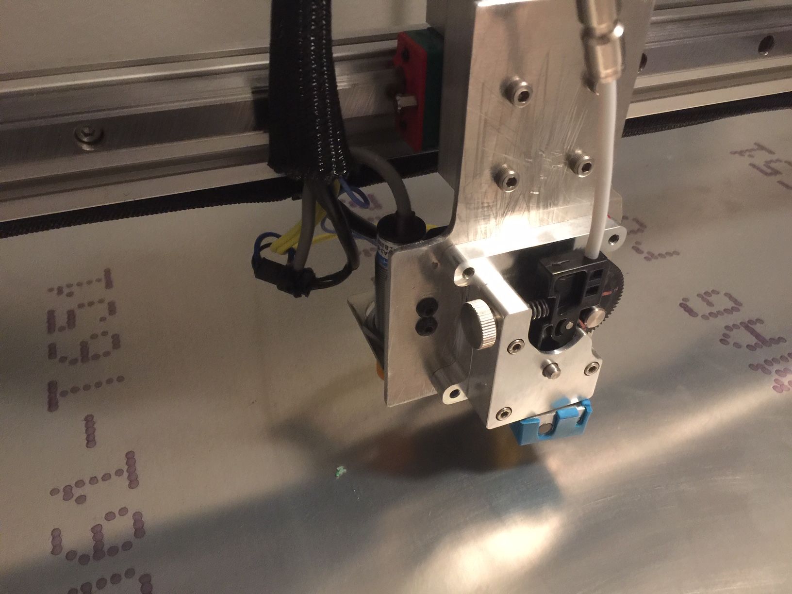
ok, I just modified the code once again. Changed the value of the steps to 1600 using the formula. Im not sure if the direction is correct. The x axis travels to the left and homes to the right as you see in the photo, the hotend is at 0 and the z probe is to the opposite side (left). currently the x axis has triggered the endstop at 0. should i change the values to negative? So, the probe should be closest to 0 not the nozzle/hotend?
Heres the updated code:
; General preferences G90 ; send absolute coordinates... M83 ; ...but relative extruder moves M550 P"Duet 3" ; set printer name ; Drives M569 P0.2 S0 ; physical drive 0.2 goes forwards M569 P0.0 S1 ; physical drive 0.0 goes forwards M569 P0.1 S1 ; physical drive 0.1 goes forwards M569 P0.3 S0 ; physical drive 0.3 goes forwards M584 X0.2 Y0.0 Z0.1 E0.3 ; set drive mapping M350 X16 Y16 Z16 E16 I1 ; configure microstepping with interpolation M92 X1600.00 Y1600.00 Z1600.00 E873.00 ; set steps per mm M566 X300.00 Y300.00 Z300.00 E400.00 ; set maximum instantaneous speed changes (mm/min) M203 X950.00 Y950.00 Z950 950.00 ; set maximum speeds (mm/min) M201 X300.00 Y300.00 Z300.00 E400.00 ; set accelerations (mm/s^2) M906 X1500 Y1500 Z1700 E900 I30 ; set motor currents (mA) and motor idle factor in per cent M84 S30 ; Set idle timeout ; Axis Limits M208 X-0 Y-0 Z-0 S1 ; set axis minima M208 X900 Y700 Z860.16 S0 ; set axis maxima ; Endstops M574 X1 S1 P"io2.in" ; configure active-high endstop for low end on X via pin io2.in M574 Y1 S1 P"io4.in" ; configure active-high endstop for low end on Y via pin io4.in M574 Z2 S1 P"io1.in" ; configure active-high endstop for high end on Z via pin io1.in ; Z-Probe M558 P5 C"!io5.in" H5 F120 T9000 ; set Z probe type to switch and the dive height + speeds G31 P500 X45 Y40 Z0.15 ; set Z probe trigger value, offset and trigger height M557 X0:900 Y0:700 S40 ; define mesh grid ; Heaters ;M308 S1 P"temp1" Y"thermistor" T100000 B3950 ; configure sensor 0 as thermistor on pin temp1 ;M950 H1 C"out0" T1 ; create bed heater output on out0 and map it to sensor 1 ;M307 H1 B1 S1.00 ; enable bang-bang mode for the bed heater and set PWM limit ;M140 H1 ; map heated bed to heater 0 ;M143 H1 S120 ; set temperature limit for heater 0 to 120C M308 S0 P"temp0" Y"thermistor" T100000 B4725 C7.06e-8 ; configure sensor 1 as thermistor on pin temp0 M950 H0 C"out1" T0 ; create nozzle heater output on out1 and map it to sensor 0 M307 H0 B0 S1.00 ; disable bang-bang mode for heater and set PWM limit ; Fans M950 F0 C"out9" Q500 ; create fan 0 on pin out9 and set its frequency M106 P0 S0 H0 T45 ; set fan 0 value. Thermostatic control is turned on M950 F1 C"out8" Q200 ; create fan 1 on pin out8 and set its frequency M106 P1 S1 H0 T45 ; set fan 1 value. Thermostatic control is turned on ; Tools M563 P0 S"Extruder 1" D0 H0 F0 ; define tool 0 G10 P0 X0 Y0 Z0 ; set tool 0 axis offsets G10 P0 R0 S0 ; set initial tool 0 active and standby temperatures to 0C ; Custom settings are not defined ; Miscellaneous M501 ; load saved parameters from non-volatile memory M911 S10 R11 P"M913 X0 Y0 G91 M83 G1 Z3 E-5 F1000" ; set voltage thresholds and actions to run on power loss -
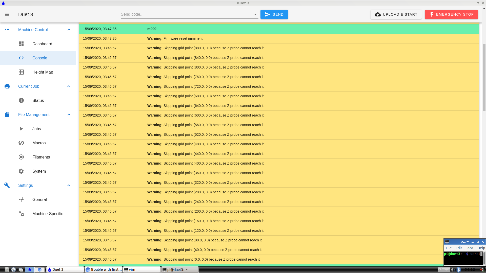
I'm not sure if my offset is correct to the actual position of the hot end or z probe. i tried to use g29 mesh compensation but the message i get is that the certain points aren't reachable. Also I believe I set the 0.0 point to the correct position of the bed.
-
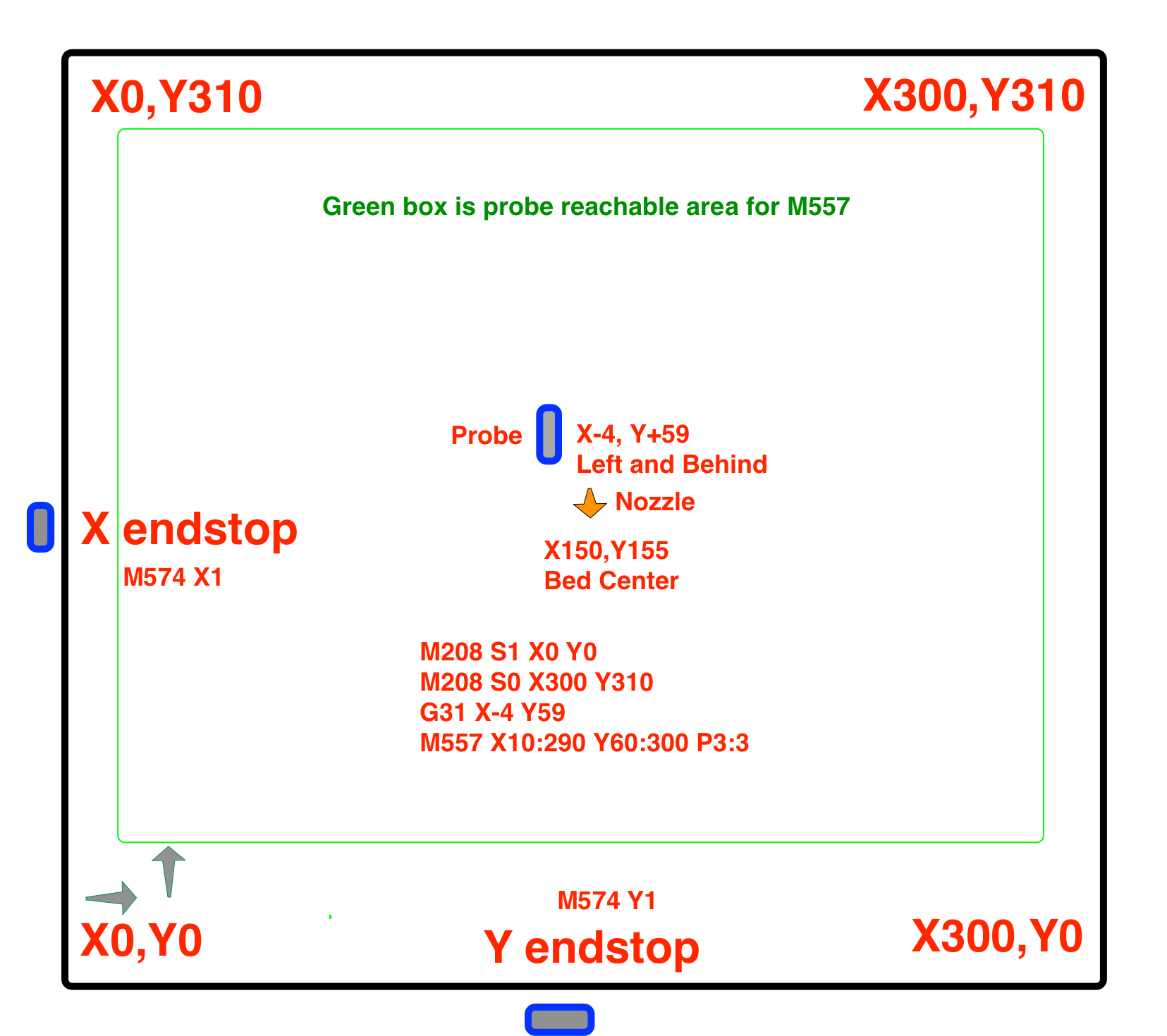
I suggest you make yourself a diagram like this to help visualize the bed/endstop/probe/coordinate system.
Based on your description of the X endstop being on the right side (the high end of travel) it should be setting the position to the high end when it triggers and the homing direction should be positive. So it would be M574 X2.
; Endstops M574 X2 S1 P"io2.in" ; configure active-high endstop for low end on X via pin io2.in M574 Y1 S1 P"io4.in" ; configure active-high endstop for low end on Y via pin io4.in M574 Z2 S1 P"io1.in" ; configure active-high endstop for high end on Z via pin io1.in And then based on your photo the probe is to the left of the nozzle so the X offset would be negative.
-
Ok, so I looked over the diagram you provided me with, it looks like I have the coordinates set correctly. I just tried to print the cube for the calibration test and it’s looking terrible, it went to the center and started printing the outside layer and worked it’s way to the center. I’m just glad that it’s actually printing something. Thanks to all the help and this is a video of it printing the first layer which ended up lifting of the bed. I don’t have the bed heater hooked up. So I’ll just hold off on printing until I hook up the heater and start the test print once again. Still have a lot of work to do. Really appreciate the help guys!

-
If it's moving with some approximation of accuracy and squirting plastic, that's a win!
-
@1997alex said in Trouble with first test print:
M208 X-0 Y-0 Z-0 S1
Set this to
M208 X0 Y0 Z0 S1. Don't use '-' between parameters unless you actually mean "negative-something".I'm not sure if my offset is correct to the actual position of the hot end or z probe.
Your current setting seems to be:
G31 P500 X45 Y40 Z0.15
From your picture, and assuming that X0 Y0 is front left of your bed, the probe is to the left and behind the nozzle. To work out the probe offset values, imagine the nozzle is at X0 Y0. Where would the probe be? In your case, X-45 Y40 I think. So try
G31 P500 X-45 Y40 Z0.15.M557 X0:900 Y0:700 S40
Because of the probe offset, and the bed limits you have set with M208, some points are unreachable by the probe. With the above probe offset, you can't get to the 45mm on the right hand side of the bed (because the probe is at X-45), or the front 40mm of the bed (because probe is at Y40). Then give the edge a couple of mm clearance. So set M557 to
M557 X5:850 Y45:700 S40.If your nozzle can reach points outside the bed, you can adjust M208, eg if it can go off the front by 20mm, change M208 to
M208 X0 Y-20 Z0 S1. Then adjust M557 so that the probe can get closer to the edge, egM557 X5:850 Y25:700 S40This is also covered here: https://duet3d.dozuki.com/Wiki/Test_and_calibrate_the_Z_probe#Section_Measuring_Probe_X_Y_Offset
https://duet3d.dozuki.com/Wiki/Using_mesh_bed_compensationIan