FAN1 suddenly stop working
-
So, my Duet wifi has been working smoothly for the past 6 months, but from one moment to the next FAN1 (default hotend) stopped working. To test if the problem would be the fan itself, I defined on config FAN2 as the tool fan and it worked perfectly. The problem then would be the board.
After some research I saw that the mosfet tends to burn in case of a short. I went to examine it and didn't see any burn mark on it. So I switched back the config for FAN1 and measured the fan output voltage with a multimeter, both with a cold hotend and at 50ºC, and the most curious thing is that regardless of whether the fan is supposedly on or off, the voltage is always 24V ( but if it's always 24V, shouldn't the fan work?)
Does anyone have any idea what might be happening?
I can always use FAN2 but I want to be able to have a second hotend.
Thanks -
Please post your config.g
-
@Major said in FAN1 suddenly stop working:
most curious thing is that regardless of whether the fan is supposedly on or off, the voltage is always 24V
duet switches on the negative side. so the Voltage is always Vin (or 5v if you selected it)
-
@Phaedrux this is my config.g before changed the tool to FAN2.
; Configuration file for Duet WiFi (firmware version 2.03)
; executed by the firmware on start-up
;
; generated by RepRapFirmware Configuration Tool v2.1.8 on Sun Apr 12 2020 17:33:38 GMT+0100 (Hora de verão da Europa Ocidental); General preferences
G90 ; send absolute coordinates...
M83 ; ...but relative extruder moves
M550 P"3DMajor" ; set printer nameM667 S1 ; select CoreXY mode
; Network
M552 S1 ; enable network
M586 P0 S1 ; enable HTTP
M586 P1 S0 ; disable FTP
M586 P2 S0 ; disable Telnet; Drives
M569 P0 S0 ; physical drive 0 goes backwards
M569 P1 S0 ; physical drive 1 goes backwards
M569 P2 S1 ; physical drive 2 goes forwards
M569 P3 S0 ; physical drive 3 goes backwards
M584 X0 Y1 Z2 E3 ; set drive mapping
M350 X16 Y16 Z16 E16 I1 ; configure microstepping with interpolation
M92 X160.00 Y160.00 Z1600.00 E802 ; set steps per mm
M566 X900.00 Y900.00 Z60.00 E3000.00 ; set maximum instantaneous speed changes (mm/min)
M203 X25000.00 Y25000.00 Z600.00 E3000.00 ; set maximum speeds (mm/min)
M201 X1500.00 Y1500.00 Z240.00 E10000.00 ; set accelerations (mm/s^2)
M906 X1450 Y1450 Z1600 E1450 I30 ; set motor currents (mA) and motor idle factor in per cent
M84 S30 ; Set idle timeout; Axis Limits
M208 X-5.5 Y0 Z0 S1 ; set axis minima
M208 X400 Y407.3 Z480 S0 ; set axis maxima; Endstops
M574 X1 Y2 S0 ; set active low and disabled endstops
M574 Z1 S2 ; set endstops controlled by probe; Z-Probe
M307 H3 A-1 C-1 D-1 ; disable heater on PWM channel for BLTouch
M558 P9 H3 F60 T12000 ; set Z probe type to bltouch and the dive height + speeds
G31 P500 X30 Y1.5 Z1.15 ; set Z probe trigger value, offset and trigger height
M557 X25:375 Y25:375 S50 ; define mesh grid; Heaters
M140 H0 ; remap heated bed to heater 2
M307 H0 B1 S1.00 ; enable bang-bang mode for the bed heater and set PWM limit
M307 H1 A298.4, C189.5, D2.5 S1 ; heater 1 (hotend) PID tunning
M305 P1 T100000 B4725 C7.060000e-8 R4700 ; set thermistor + ADC parameters for heater 1
M143 H1 S300 ; set temperature limit for heater 1 to 280C
M305 P0 T100000 B3950 R4700 ; set thermistor + ADC parameters for heater 2
M143 H0 S130 ; set temperature limit for heater 2 to 130C; Fans
M106 P0 S0 I0 F500 H-1 ; set fan 0 value, PWM signal inversion and frequency. Thermostatic control is turned off
M106 P1 S1 I0 F500 H1 T45 ; set fan 1 value, PWM signal inversion and frequency. Thermostatic control is turned on; Tools
M563 P0 D0 H1 F0 ; define tool 0
G10 P0 X0 Y0 Z0 ; set tool 0 axis offsets
G10 P0 R0 S0 ; set initial tool 0 active and standby temperatures to 0C;Filament Runout Sensor
M591 D0 P2 C3 S1 ;Define Filament sensor Extruder0; Custom settings are not defined
; Miscellaneous
M911 S10 R11 P"M913 X0 Y0 G91 M83 G1 Z3 E-5 F1000" ; set voltage thresholds and actions to run on power loss -
@Veti I have the jumper to use Vin (24V) so that explains the voltage there. But what is scratching my head is, if I have 24v there, why when I connect a fan (which I know is working) it does nothing. My knowledge of electronics is basic, maybe someone more knowledgeable can explain to me why that happens.
-
@Major said in FAN1 suddenly stop working:
; Fans
M106 P0 S0 I0 F500 H-1 ; set fan 0 value, PWM signal inversion and frequency. Thermostatic control is turned off
M106 P1 S1 I0 F500 H1 T45 ; set fan 1 value, PWM signal inversion and frequency. Thermostatic control is turned on
; Tools
M563 P0 D0 H1 F0 ; define tool 0Well your current config has fan0 as part cooling fan and assigned to the tool. So it should work with the slider in DWC or by sending M106 P0 S1.
Fan1 is set as thermostatic control for the hotend to turn on above 45c.
There is no config for fan2.
Are you saying that the hotend fan doesn't turn on above 45c?
If you send M106 P1 H-1 S1 does it turn on?
-
Fan1 is set as thermostatic control for the hotend to turn on above 45c.
There is no config for fan2.
Are you saying that the hotend fan doesn't turn on above 45c?
If you send M106 P1 H-1 S1 does it turn on?
Until the beginning of this week everything was working well with the config.g that I posted. From one moment to the next it stopped working.
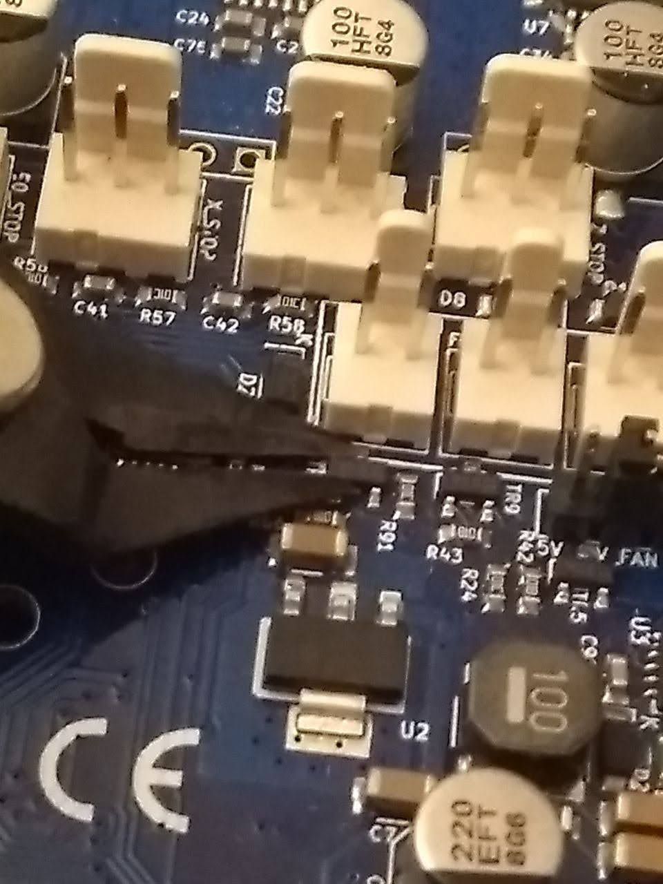
What I noticed in the meantime is that the cable extension I used for the fan stopped working. There may have been a short that I didn't notice. Visually I don't see anything burned (as in the examples I saw here on the forum). I'll attatch a photo of my duet board (if relevant, my board version is 1.04b)

Now the fan does not work even if the heater temperature rises above 45º.
I tried to send M106 P1 H-1 S1 as suggested and the fan still doesn't work. I used a multimeter to measure the voltage at the FAN1 output and when it should be switched off, the voltage is 24V and after sending the command the voltage dropped to 20.7V.
The strange thing, at least for me, is that if I have current why the fan doesn't work.
In the meantime I changed in config.g to use FAN2 for the hotend and everything is working fine, but I want to repair the FAN1 output.
Could it be a Mosfet problem?
Thanks -
@Major said in FAN1 suddenly stop working:
Could it be a Mosfet problem?
Yes it sounds like that may be the case. If there was a short in your cabling it's possible even if you can't visually see an exploded mosfet. They don't always fail spectacularly.
If the exact same fan works on fan2 but not on fan1 with the same configuration, then it's pretty likely it's the mosfet.
They can be replaced if you have the skills and equipment, but not for beginners IMO.
-
@Phaedrux said in FAN1 suddenly stop working:
They can be replaced if you have the skills and equipment, but not for beginners IMO.
Fortunately I already have some experience soldering and doing some rework (some time ago I started to build guitar effects pedals) and I also had some experience with SOT23 components.
My fear is that there are so many components so close to the mosfet. But I think I'll order some replacements and try my luck.
Thanks for all the help. -
@Major said in FAN1 suddenly stop working:
My fear is that there are so many components so close to the mosfet.
I've heard of kapton tape being used as a heat shield.
-
@Major said in FAN1 suddenly stop working:
My fear is that there are so many components so close to the mosfet.
If you are using hot air equipment, then the main problem is that the plastic parts of the nearby fan outputs and jumper blocks will be scorched. You can avoid this in a couple of ways:
-
Pull the plastic parts off with pliers (for the Molex connectors, it's easier if you heat the pins using ~180C hot air first), and replace them when you have replaced the mosfets and tested the fix.
-
Shield the plastic parts. I generally use 2 layers of masking tape and a top layer of Kapton tape.
You don't need to worry about heating other nearby SMD parts as long are you are careful not to jog them while the solder is molten.
When replacing 0603 and SOT23 components, I often remove the old part using hot air but use a fine-tipped soldering iron to fit the new ones. A no-clean flux pen makes it easier.
HTH David
Duet WiFi hardware designer and firmware engineer
Please do not ask me for Duet support via PM or email, use the forum
http://www.escher3d.com, https://miscsolutions.wordpress.com -
-
Alternatively if you don't have hot air and don't mind being a bit of a savage ... you might be able to put a blob of solder on a sufficiently tip and just cover the whole part you want to remove with the blob of molten solder and when you lift the iron the part will stick to the surface tension of the solder blob.
It helps to make sure you can touch the pads, so lifting the plastic shroud of the molex connector can help in desoldering and is almost a must for soldering in the new unless you have a very fine tip iron.
If the blob trick doesn't work, you can crank the savage factor up to 11 and try literally "decapitating" the poor little SOT23, exposing the die and leads makes it a lot easier to pull with a good sized tip and blob of solder, make sure to use flush side cutters to avoid any forces lifting up from the board and try something like
-
@Phaedrux said in FAN1 suddenly stop working:
I've heard of kapton tape being used as a heat shield.
yes, i read a post from David talking about it.
-
@dc42 said in FAN1 suddenly stop working:
If you are using hot air equipment, then the main problem is that the plastic parts of the nearby fan outputs and jumper blocks will be scorched.
Unfortunately I don't have a hot air gun. I will have to do everything with the soldering iron, but I'm thinking about ordering some Chip Quik to make it easier.
And i will use your use Kapton tape technique.
Thanks. -
@bearer said in FAN1 suddenly stop working:
Alternatively if you don't have hot air and don't mind being a bit of a savage ... you might be able to put a blob of solder on a sufficiently tip and just cover the whole part you want to remove with the blob of molten solder and when you lift the iron the part will stick to the surface tension of the solder blob.
Thank you for the advice. As I do not have a hot air gun, I may as well use this technique.
If the blob trick doesn't work, you can crank the savage factor up to 11 and try literally "decapitating" the poor little SOT23
I hope I don't have to get to that point. But let's see how it goes.