Direction Change Print Quality Issues?
-
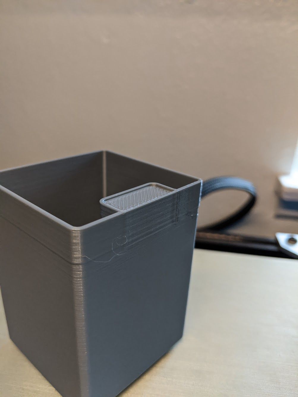
I'm noticing this effect on any prints with direction changes in them. Any thoughts on what could be causing it? D-bot CoreXY.
Its not the z axis I can absolutely promise that doesn't have any play with the linear rails.
PID tune is a-okay
I'm thinking accel/jerk/speed issue, but i cant find any similar issues online.The line going all the way around is from the slicer. Idk why but that's not the main focus. The main focus is where the tab prints and leaves a z-banding looking issue.

; Configuration file for Duet WiFi (firmware version 1.20 or newer) ; executed by the firmware on start-up ; ; generated by RepRapFirmware Configuration Tool on Thu Jun 21 2018 19:14:32 GMT-0700 (Pacific Daylight Time) ;------------------------------------------------------------------------------------------------------------------ ; General preferences G90 ; Send absolute coordinates... M83 ; ...but relative extruder moves M667 S1 ; Select CoreXY mode ; Network M550 PBlue the D-Bot ; Set machine name M552 S1 ; Enable network M586 P0 S1 ; Enable HTTP M586 P1 S0 ; Disable FTP M586 P2 S0 ; Disable Telnet ; Drives M569 P0 S1 ; Drive 0 goes forwards M569 P1 S1 ; Drive 1 goes forwards M569 P2 S1 ; Drive 2 goes forwards M569 P3 S0 ; Drive 3 goes forwards M569 P4 S1 ; Drive 4 goes forwards M350 X16 Y16 Z16 E16 I1 ; Configure microstepping with interpolation M92 X100 Y100 Z414.5 E394 ; :870(E2) ; Set steps per mm (Start:Z415) (chimera value 870) ;M579 X1 Y1 Z1.00301205 ; Set axis scaling factors M566 X700 Y700 Z240 E1000 ; Set maximum instantaneous speed changes (mm/min) (OG E600:600) M203 X18000 Y18000 Z2400 E3600 ; Set maximum speeds (mm/min) M201 X800 Y800 Z250 E3000:3000 ; Set accelerations (mm/s^2) M906 X1500 Y1500 Z1200 E850:850 I50 ; Set motor currents (mA) and motor idle factor in percent M84 S30 ; Set idle timeout ; Axis Limits M208 X0 Y-10 Z0 S1 ; Set axis minima (chimera/original y value = 0) M208 X300 Y185 Z300 S0 ; Set axis maxima ; Endstops M574 X1 Y2 S0 ; Set endstops controlled by endstops ;M574 X1 Y2 S0 ; Set endstops controlled by motor load detection ; Z-Probe M574 Z1 S2 ; Set endstops controlled by probe M307 H3 A-1 C-1 D-1 M558 P9 H5 F750 T7200 G31 X25.9 Y0 Z02.42 P25 ; Probe Offset - Increase for Nozzle down, Decrease for Nozzle up (chimera value .6) M557 X26:280 Y5:185 S50:45 ; Define mesh grid ; Heaters ; Heater 0 (Bed) M305 P0 T100000 B3950 C0 R4700 ; Set thermistor + ADC parameters for heater 0 M143 H0 S110 ; Set temperature limit for heater 0 to 110C ; Heater 1 (Extruder) M305 P1 T100000 B4725 C7.06e-8 R4700 ; Set thermistor + ADC parameters for heater 1 M143 H1 S275 ; Set temperature limit for heater 1 to 275C ; Heater 2 (disable for Titan Aero) ;M305 P2 T100000 B4138 C0 R4700 ; Set thermistor + ADC parameters for heater 2 ;M143 H2 S275 ; Set temperature limit for heater 2 to 275C ; Fans M106 P0 S0 I0 F500 H-1 ; Set fan 0 value, PWM signal inversion and frequency. Thermostatic control is turned off M106 P1 S165 T55 H1:2 ; Set fan 1 value, PWM signal inversion and frequency. Thermostatic control is turned off M106 P2 S0 I0 F500 H-1 ; Set fan 2 value, PWM signal inversion and frequency. Thermostatic control is turned off ; Tools M563 P0 D0 H1 ; Define tool 0 G10 P0 X0 Y0 Z0 ; Set tool 0 axis offsets G10 P0 R0 S0 ; Set initial tool 0 active and standby temperatures to 0C ;------------------------------------------------------------------------------------------------------------------ ; Next 3 lines are for Chimera config. Disabled for Titan Aero ; IMPORTANT: Titan Aero Thermistors are swapped at the board. Swap them back for Chimera Use. NOT THE CASE FOR V2 ;------------------------------------------------------------------------------------------------------------------ ;M563 P1 D1 H2 ; Define tool 1 ;G10 P1 X9 Y0 Z0 ; Set tool 1 axis offsets ;G10 P1 R0 S0 ; Set initial tool 1 active and standby temperatures to 0C ; Automatic saving after power loss is not enabled ; Custom settings are not configured M501 ; Miscellaneous T0 ; Select first tool. Change to T-1 for use with Chimera -
Try X/Y acceleration of 1500 or more. Maybe reduce X/Y jerk to 400 or less
-
@oliof Slight improvement but still significant change in surface quality
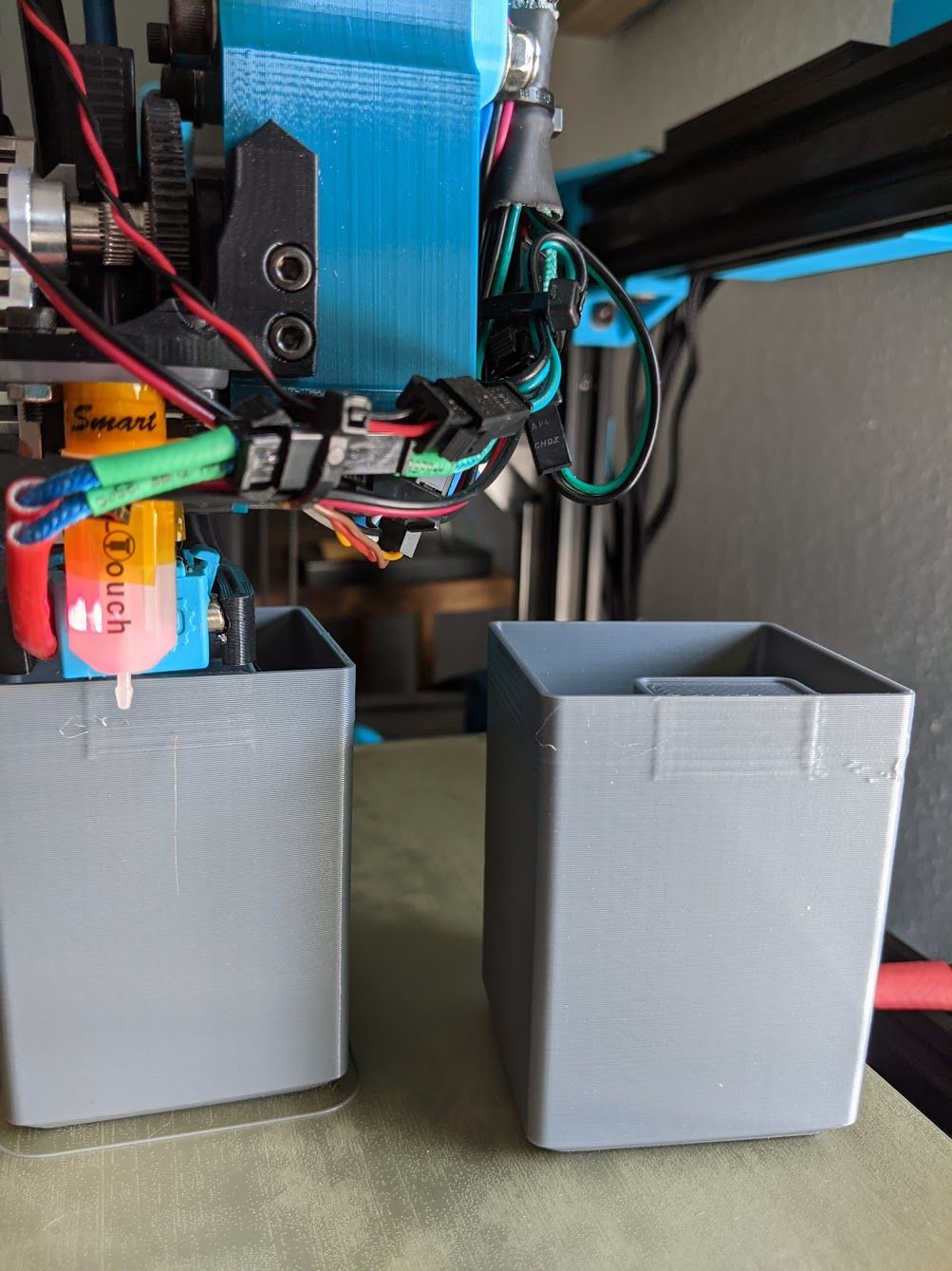
on the right is the old one. One printing on right is with 400 jerk and 1500 accel

-
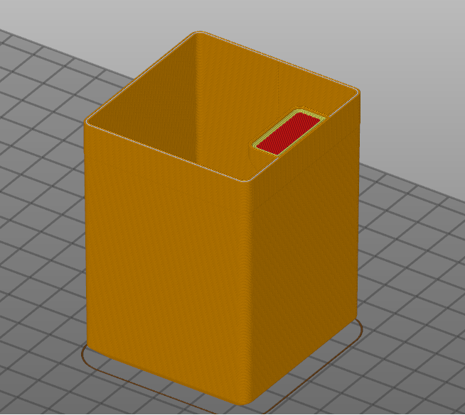
What does the gcode visualization preview in the slicer look like?
-
-
Well I think you can see the difference right there. On the walls there is gap fill, and on the bump out there is none. Try turning off thin wall detection in the slicer. You may need to adjust your extrusion width up or down to get 2 extrusion paths to fit into the area of the thin wall.
-
@Phaedrux gotcha. will report when done. Although this issue also occurs on regular prints with direction changes. No gap fill usually. will see
-
@Phaedrux significantly worse print quality overall.
Not the best lighting but its what I've got
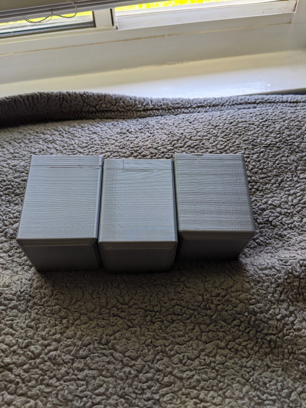
right-most one is with thin wall detection disables and no gap fill due to lower line width value

-
Thin walls are a tough nut for slicers to deal with.
I suggest you try the Super Slicer fork of Prusa Slicer. It has a few extra options for how thin walls are handled that might help eliminate the bumps. One of the options is to treat the thin sections as a connected part of the attaching walls rather than a seperate wall section that buts up against it.
It might also help to try forcing the seam to either aligned or to the rear.
-
@Phaedrux just thought of something. Is it possible that it has to do with some sort of overlap between inner walls/infill with the outer walls? that could explain why my thin walled prints look good, whereas anything else not so much
