Inconsistent results with optical encoder wheel filament sensor
-
@JohnOCFII saleae 8 uses the CY7C68013A mcu. That series of cypress mcu's have 8051 compatible core and a way to directly copy a port on to usb at 24MHz so to have 24 MHz pass trough 8 bit logic analyzer you just need that mcu + some input handling
")
I'm not sure if they configure trigger condition on the '51 or they do it in software
Their 16pin version comes with fpga and does not work the same but I don't have 16pin version so no clue how exactly it works nor what it supports. For more than pins I use obls or I use my trusty 400MHz agilent mxo

-
@JohnOCFII said in Inconsistent results with optical encoder wheel filament sensor:
If I held the encoder wheel tightly, I could move the filament past the TPU wheel with less force than I expected.
so if the dirt gets in, wheel get stuck, it will slip ?
I'll give that a shot. I need to make sure that I can do something that doesn't make the encoder wheel much wider, as the channel is pretty thin.
IMHO you can sand off 1mm from the side of the wheel where you will apply alu tape. IIRC alu tape is .25mm thick so that should do it.
-
@arhi said in Inconsistent results with optical encoder wheel filament sensor:
@JohnOCFII saleae 8 uses the CY7C68013A mcu. That series of cypress mcu's have 8051 compatible core and a way to directly copy a port on to usb at 24MHz so to have 24 MHz pass trough 8 bit logic analyzer you just need that mcu + some input handling
Do you need extra hardware, or is it just a matter of connecting one lead from the Saleae to the signal pin on the optical encoder (in this case) and a different lead to the appropriate signal pin on the Duet, and setting the software to "passthrough from lead x to lead y?
-
@arhi said in Inconsistent results with optical encoder wheel filament sensor:
@JohnOCFII said in Inconsistent results with optical encoder wheel filament sensor:
If I held the encoder wheel tightly, I could move the filament past the TPU wheel with less force than I expected.
so if the dirt gets in, wheel get stuck, it will slip ?
Yes, especially with the Bondtech extruder pulling as strongly as it does.
I'll give that a shot. I need to make sure that I can do something that doesn't make the encoder wheel much wider, as the channel is pretty thin.
IMHO you can sand off 1mm from the side of the wheel where you will apply alu tape. IIRC alu tape is .25mm thick so that should do it.
The encoder wheel is only 1mm thick...
I'm going to have to think about this...
")
Thanks for your ideas and input!
-
@JohnOCFII said in Inconsistent results with optical encoder wheel filament sensor:
The encoder wheel is only 1mm thick...
looks thicker on the picture
.. anyhow, if you have aluminium tape, you can stick it on one side, cut, then sand plastic side till it fits the groove properly... the alu tape is rather thin so it is easy to sand off that much from the plastic side.Do you need extra hardware, or is it just a matter of connecting one lead from the Saleae to the signal pin on the optical encoder (in this case) and a different lead to the appropriate signal pin on the Duet, and setting the software to "passthrough from lead x to lead y?
the saleae has the "extra hardware" as the input circuitry (iirc there's octal bus transciever or something like that making it work ok with 3v3 and 5v signals) so what you would do is connect GND from saleae to GND on the duet and S1 from the saleae to the connlcd.encb set the sw to start scanning at some lower freq (no need to do 25MHz, 100Hz is more than enough I think, maybe 1kHz) and let it scan for couple of minits during printing and then you click stop and analyze the trace.
-
@arhi said in Inconsistent results with optical encoder wheel filament sensor:
@JohnOCFII said in Inconsistent results with optical encoder wheel filament sensor:
The encoder wheel is only 1mm thick...
looks thicker on the picture
.. anyhow, if you have aluminium tape, you can stick it on one side, cut, then sand plastic side till it fits the groove properly... the alu tape is rather thin so it is easy to sand off that much from the plastic side.I can also sand out the slot too -- or maybe see if @fractalengineer will share the design files so I can widen out the slot.
Do you need extra hardware, or is it just a matter of connecting one lead from the Saleae to the signal pin on the optical encoder (in this case) and a different lead to the appropriate signal pin on the Duet, and setting the software to "passthrough from lead x to lead y?
the saleae has the "extra hardware" as the input circuitry (iirc there's octal bus transciever or something like that making it work ok with 3v3 and 5v signals) so what you would do is connect GND from saleae to GND on the duet and S1 from the saleae to the connlcd.encb set the sw to start scanning at some lower freq (no need to do 25MHz, 100Hz is more than enough I think, maybe 1kHz) and let it scan for couple of minits during printing and then you click stop and analyze the trace.
Cool. I might just have to upgrade. I see they have "Enthusiast Pricing" for the basic Logic 8.
-
well the saleae software is very very very good (better than most I tried, maybe the best) but hw prices are not very popular, logic8 is $400 while clone that features 90% identical hw is $7 (the clone is only missing a few $ worth parallel adc to have analog channel instead of 8 digital ones)... the logic16 is $1000 .. that's really high ... no it should have unlimited depth trough usb3 at 100mhz but ... for $1k ..
-
@arhi said in Inconsistent results with optical encoder wheel filament sensor:
well the saleae software is very very very good (better than most I tried, maybe the best) but hw prices are not very popular, logic8 is $400 while clone that features 90% identical hw is $7 (the clone is only missing a few $ worth parallel adc to have analog channel instead of 8 digital ones)... the logic16 is $1000 .. that's really high ... no it should have unlimited depth trough usb3 at 100mhz but ... for $1k ..
Looks like Enthusiasts can get the Logic 8 for half price:
https://blog.saleae.com/saleae-discounts/
I value good software, and will pay for it.
-
@JohnOCFII $200 is totally acceptable ... I don't remember how much I paid for mine (I think it was 300eur but not sure) but I needed a throughput then so much I was willing to pay even more as I had a choice - a ready-made device with working SW, or making one from arm32 with software from scratch, 300eur was waaaaaaaaaaaaaay cheaper than me making it from scratch and OBLS while superbly good could not get the job done as I needed depth (and even chained 3 obls's I have could not cut it). few other logic analyzers use almost identic schematic as logic8 ... anyhow getting too much off-topic
my idea of using logic analyzer here, low scan frequency needed only, 1 channel, so could probbly made using arduino board, is to grab signals from a probe during "constant extrusion time" ... so if you know that next "minute" the extrusion will be "constant"
- reset the sensor data on the duet (by issuing
M591 D0 P7 C"connlcd.encb" S0 R50:1500 L1.2 E5 A1or what is your filament sensor config line) - start recording
- wait a minute
- stop recording and read filament data
now compare min/max with what you read from the logic analyzer.
analyze jitter in the impulses you read from the probe - you should have pulses evenly spaced. if you see pulses "too close to one another" or pulses missing those are either errors from the sensor or errors in g-code (extrusion is not that constant as you would expect - this will happen often with shitty slicers).One other thing that's possible requires some disassembling or using spare parts. That's what I'd do
- make a logic analyzer out of some arduino board or similar (no need for MHz speed so no need for a few hundred bucks worth of LA for this purpose, by all means, if you need a good LA saleae is great, dl the sw to test it works without LA in demo mode, you will love it )
- feed filament trough your sensor
- feed filament into extruder (you said you use bondtech)
- remove hotend, so filament is now just going out of the extruder, no melting...
- make your own g-code to something like this
M302 P1 ; Allow cold extrusion G92X0Y0Z0 ; duet now assume we are homed M82 ; extruder absolute position G92E0 ; reset extruder to 0 M591 D0 P7 C"connlcd.encb" S0 R50:1500 L1.2 E5 A1 ; config filament sensor G1 E1000 F120 ; extrude 1000mm at 2mm/sec, so will be extruding around 8 minutes M591 ; query filament sensor - mark the filament with a marker at exit point of the extruder
- execute this code as gcode file (you need to start print for filament to actually work)
- while code is running log the impulses with logic analyzer
- when code finish, mark the filament at exit point of the extruder
now you
- analyze logic analyzer output
- look at the readout of the m591
- measure the exact length of the filament extruder with a meter (you have two marks on it) and compare to M591 output (over xxx mm value)
- reset the sensor data on the duet (by issuing
-
@arhi said in Inconsistent results with optical encoder wheel filament sensor:
@JohnOCFII $200 is totally acceptable ...
I filled out the form to see if I get approved for the discount from Saleae. I'm sure I could use the BitScope as well, but not too keen on spending time getting familiar with abandon-ware.
now you
- analyze logic analyzer output
- look at the readout of the m591
- measure the exact length of the filament extruder with a meter (you have two marks on it) and compare to M591 output (over xxx mm value)
Kind of going down the rabbit hole at this point, but heh -- what else is there to do as the weather turns cold!
Progress may be slow at times, as my employer does expect a little something now and then.
John
-
@JohnOCFII well, making analyzer out of the arduino board can be fun
I think I might take that as one of the future projects to play with .. there's a "decent" (far from great, decades away from saleae ) software that's kinda universal for logic analyzers, we used it for obls (I was for a very short while doing some dev for the obls and bus blaster many many years ago) called SUMP Logic Analyzer. I'm sure it got better, last time I checked it out was I think 10 years ago so, if it is still alive it might be good, last time I used it was decent / acceptable, there was also a fork with bunch of decoders and some other SUMP compatible software you might wanna check out http://dangerousprototypes.com/docs/Client_that_work_with_the_Open_Logic_Sniffer ..Now, it might be possible to clone the type 7 of the logic probe to a type 8 of the logic probe directly in the RRF and make the RRF log the impulses it's getting from the probe shooting it to a debug port/serial/console in some "timestamp" format so no external hw is required. That could show exactly what RRF is seeing, and how constant these impulses are.
Another thing, without even extruder attached, just connecting a frequency generator to the connlcd.encb running a code like I shown and hitting the encb with a constant pulse generator, might also show some results...
But I still think most probably the problem is the IR transparency of the disk and all this other stuff is totally overkill
-
btw looking at this: https://github.com/Duet3D/RepRapFirmware/pull/176
they are mentioning shitty pulse generation from optical encoder
If you have a scope, checking out how a single impulse looks like might explain stuff, ignore duet, just attach scope to the output of the endstop and rotate the wheel manually and look how signal looks like
-
@arhi said in Inconsistent results with optical encoder wheel filament sensor:
btw looking at this: https://github.com/Duet3D/RepRapFirmware/pull/176
they are mentioning shitty pulse generation from optical encoder
If you have a scope, checking out how a single impulse looks like might explain stuff, ignore duet, just attach scope to the output of the endstop and rotate the wheel manually and look how signal looks like
A shame that the OP didn't reply since 2018 to give an update. I'll certainly try that and report back when I get a chance.
-
@JohnOCFII I Don't have any black scrap that are 1-2mm thick and no pla at all but I just tested 2 pieces of nontransparent PETG, 1mm (silver) and 2mm (red) and oh boy they are transparent to IR ...
take a remote controller and your mobile phone and look at the front of the remote with the camera, press "volume+" or some other "non stop going" button and you should see it strobing with your camera. now put a piece of plastic 1mm thin between the camera and remote and ...
this is my test with PETG
https://youtu.be/97H7YQFgKSwand phone camera has IR filter and my remote led is not very strong (some old remote from drawer with batteries from who knows when)... on the other hand the IR receiver on the gap sensor is much more sensitive to IR .. dunno if PLA (if you printed that with PLA) is more transparent but..
-
@arhi said in Inconsistent results with optical encoder wheel filament sensor:
@JohnOCFII I Don't have any black scrap that are 1-2mm thick and no pla at all but I just tested 2 pieces of nontransparent PETG, 1mm (silver) and 2mm (red) and oh boy they are transparent to IR ...
take a remote controller and your mobile phone and look at the front of the remote with the camera, press "volume+" or some other "non stop going" button and you should see it strobing with your camera. now put a piece of plastic 1mm thin between the camera and remote and ...
this is my test with PETG
https://youtu.be/97H7YQFgKSwand phone camera has IR filter and my remote led is not very strong (some old remote from drawer with batteries from who knows when)... on the other hand the IR receiver on the gap sensor is much more sensitive to IR .. dunno if PLA (if you printed that with PLA) is more transparent but..
Fascinating! I just tested with some cut apart vase-mode prints and an IR webcam in a dark room. The light easily shined through 1 layer (about 0.42mm) and was somewhat viewable through 2 layers. I'll print up some larger disks (not in vase mode -- just to replicate what I have now in the encoder wheel) and use that with various coverings to see what happens. I have some thick "liquid electrical tape" that might work well.
https://www.homedepot.com/p/Gardner-Bender-Black-Liquid-Electrical-Tape-4-oz-LTB-400/100119178
-
@JohnOCFII dunno how the liquid tape will do against IR, note that the sensor in the end stop is much more sensitive than your phone's camera as it does not have an IR filter. ALU tape is always my go-to for these type of things. It's good for so many things around 3d printing I always stock it.
-
@arhi said in Inconsistent results with optical encoder wheel filament sensor:
@JohnOCFII dunno how the liquid tape will do against IR, note that the sensor in the end stop is much more sensitive than your phone's camera as it does not have an IR filter. ALU tape is always my go-to for these type of things. It's good for so many things around 3d printing I always stock it.
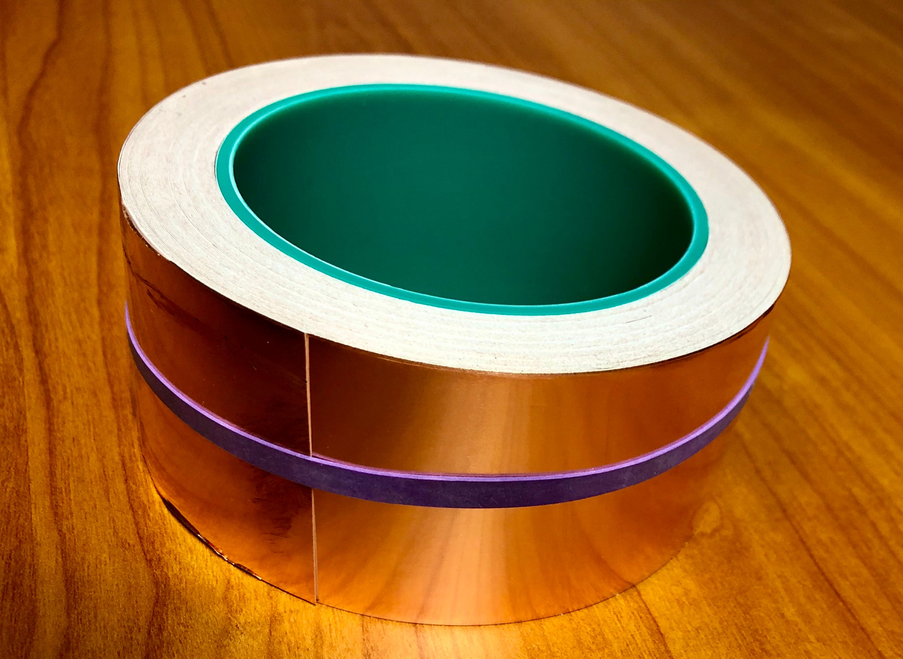
Turns out -- I had purchased a roll of copper tape to try to resolve some other 3D printing related issue a couple of years ago. I assume that'll work here in place of aluminum?

-
same thing only tad heavier
.. will work for this purpose -
@arhi said in Inconsistent results with optical encoder wheel filament sensor:
same thing only tad heavier
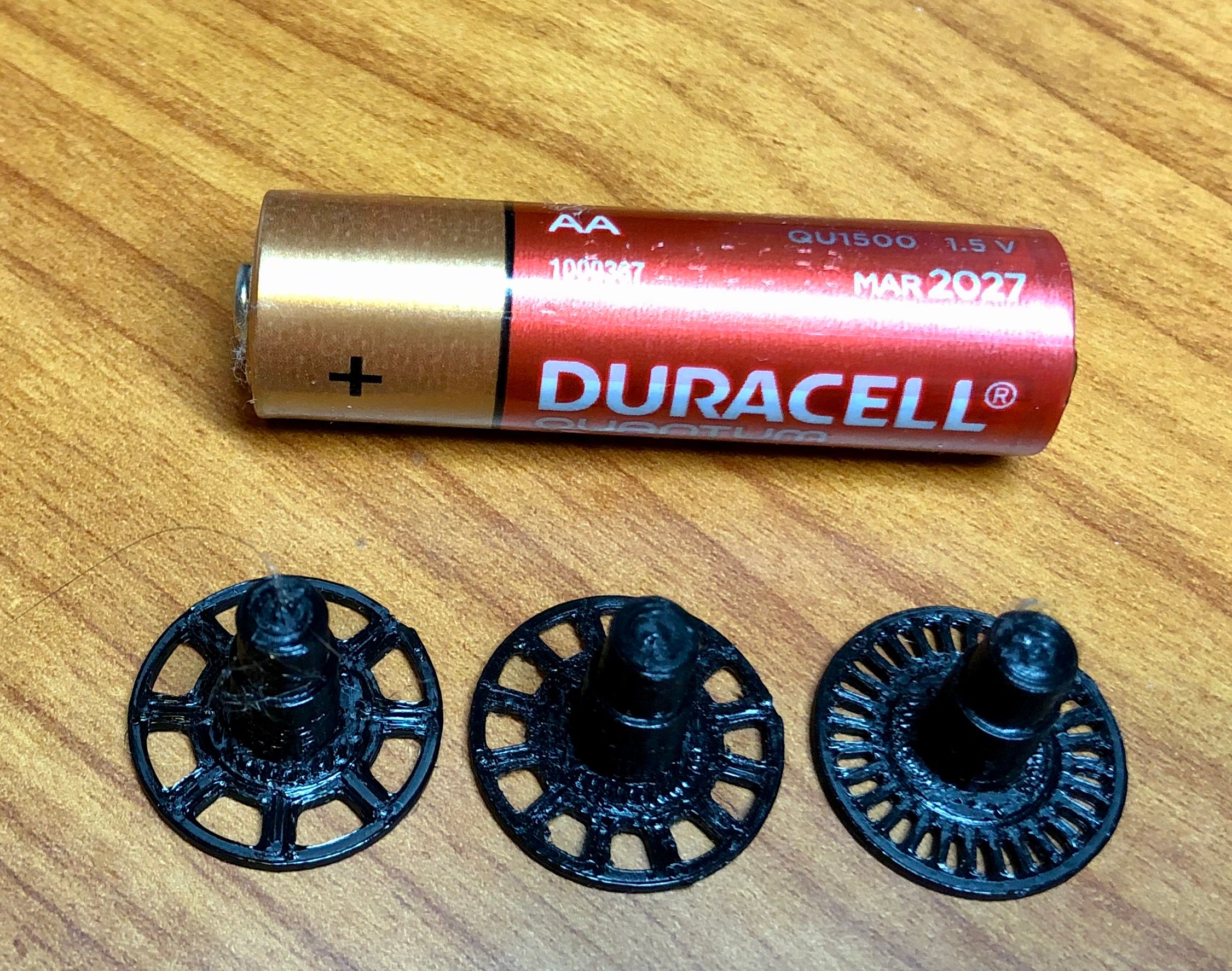
.. will work for this purposeThe encoder wheel in this design is so small -- just not sure how well any tape will work.
I'm currently running the encoder wheel in the middle - 12 spokes.

-
should work ok with the middle one, glue the tape over the back side, then cut the "windows" open with a scalpel knife, should work like a charm