Inconsistent results with optical encoder wheel filament sensor
-
@JohnOCFII well, making analyzer out of the arduino board can be fun
") I think I might take that as one of the future projects to play with .. there's a "decent" (far from great, decades away from saleae ) software that's kinda universal for logic analyzers, we used it for obls (I was for a very short while doing some dev for the obls and bus blaster
I think I might take that as one of the future projects to play with .. there's a "decent" (far from great, decades away from saleae ) software that's kinda universal for logic analyzers, we used it for obls (I was for a very short while doing some dev for the obls and bus blaster  many many years ago) called SUMP Logic Analyzer. I'm sure it got better, last time I checked it out was I think 10 years ago so, if it is still alive it might be good, last time I used it was decent / acceptable, there was also a fork with bunch of decoders and some other SUMP compatible software you might wanna check out http://dangerousprototypes.com/docs/Client_that_work_with_the_Open_Logic_Sniffer ..
Now, it might be possible to clone the type 7 of the logic probe to a type 8 of the logic probe directly in the RRF and make the RRF log the impulses it's getting from the probe shooting it to a debug port/serial/console in some "timestamp" format so no external hw is required. That could show exactly what RRF is seeing, and how constant these impulses are.
Another thing, without even extruder attached, just connecting a frequency generator to the connlcd.encb running a code like I shown and hitting the encb with a constant pulse generator, might also show some results...
But I still think most probably the problem is the IR transparency of the disk and all this other stuff is totally overkill
-
btw looking at this: https://github.com/Duet3D/RepRapFirmware/pull/176
they are mentioning shitty pulse generation from optical encoder
If you have a scope, checking out how a single impulse looks like might explain stuff, ignore duet, just attach scope to the output of the endstop and rotate the wheel manually and look how signal looks like
-
@arhi said in Inconsistent results with optical encoder wheel filament sensor:
btw looking at this: https://github.com/Duet3D/RepRapFirmware/pull/176
they are mentioning shitty pulse generation from optical encoder
If you have a scope, checking out how a single impulse looks like might explain stuff, ignore duet, just attach scope to the output of the endstop and rotate the wheel manually and look how signal looks like
A shame that the OP didn't reply since 2018 to give an update. I'll certainly try that and report back when I get a chance.
-
@JohnOCFII I Don't have any black scrap that are 1-2mm thick and no pla at all but I just tested 2 pieces of nontransparent PETG, 1mm (silver) and 2mm (red) and oh boy they are transparent to IR ...
take a remote controller and your mobile phone and look at the front of the remote with the camera, press "volume+" or some other "non stop going" button and you should see it strobing with your camera. now put a piece of plastic 1mm thin between the camera and remote and ...
this is my test with PETG
https://youtu.be/97H7YQFgKSwand phone camera has IR filter and my remote led is not very strong (some old remote from drawer with batteries from who knows when)... on the other hand the IR receiver on the gap sensor is much more sensitive to IR .. dunno if PLA (if you printed that with PLA) is more transparent but..
-
@arhi said in Inconsistent results with optical encoder wheel filament sensor:
@JohnOCFII I Don't have any black scrap that are 1-2mm thick and no pla at all but I just tested 2 pieces of nontransparent PETG, 1mm (silver) and 2mm (red) and oh boy they are transparent to IR ...
take a remote controller and your mobile phone and look at the front of the remote with the camera, press "volume+" or some other "non stop going" button and you should see it strobing with your camera. now put a piece of plastic 1mm thin between the camera and remote and ...
this is my test with PETG
https://youtu.be/97H7YQFgKSwand phone camera has IR filter and my remote led is not very strong (some old remote from drawer with batteries from who knows when)... on the other hand the IR receiver on the gap sensor is much more sensitive to IR .. dunno if PLA (if you printed that with PLA) is more transparent but..
Fascinating! I just tested with some cut apart vase-mode prints and an IR webcam in a dark room. The light easily shined through 1 layer (about 0.42mm) and was somewhat viewable through 2 layers. I'll print up some larger disks (not in vase mode -- just to replicate what I have now in the encoder wheel) and use that with various coverings to see what happens. I have some thick "liquid electrical tape" that might work well.
https://www.homedepot.com/p/Gardner-Bender-Black-Liquid-Electrical-Tape-4-oz-LTB-400/100119178
-
@JohnOCFII dunno how the liquid tape will do against IR, note that the sensor in the end stop is much more sensitive than your phone's camera as it does not have an IR filter. ALU tape is always my go-to for these type of things. It's good for so many things around 3d printing I always stock it.
-
@arhi said in Inconsistent results with optical encoder wheel filament sensor:
@JohnOCFII dunno how the liquid tape will do against IR, note that the sensor in the end stop is much more sensitive than your phone's camera as it does not have an IR filter. ALU tape is always my go-to for these type of things. It's good for so many things around 3d printing I always stock it.
Turns out -- I had purchased a roll of copper tape to try to resolve some other 3D printing related issue a couple of years ago. I assume that'll work here in place of aluminum?

-
same thing only tad heavier
.. will work for this purpose -
@arhi said in Inconsistent results with optical encoder wheel filament sensor:
same thing only tad heavier
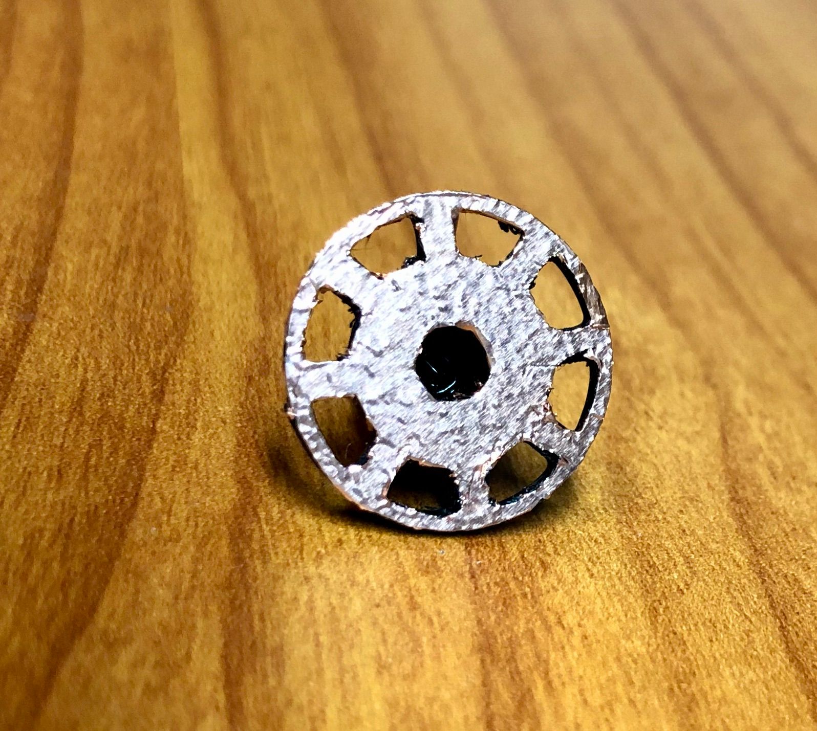
.. will work for this purposeThe encoder wheel in this design is so small -- just not sure how well any tape will work.
I'm currently running the encoder wheel in the middle - 12 spokes.

-
should work ok with the middle one, glue the tape over the back side, then cut the "windows" open with a scalpel knife, should work like a charm
-
@arhi said in Inconsistent results with optical encoder wheel filament sensor:
should work ok with the middle one, glue the tape over the back side, then cut the "windows" open with a scalpel knife, should work like a charm
Thanks for the advice. I'll try a fresh blade and give that a shot -- likely tomorrow.
-
@arhi said in Inconsistent results with optical encoder wheel filament sensor:
should work ok with the middle one, glue the tape over the back side, then cut the "windows" open with a scalpel knife, should work like a charm
That wasn't as tricky as I thought it'd be. I do think I'll try it again with a fresh X-Acto blade.
-
that should work like a charm, no transparency there now. the only question now is, will it provide a better readout now - was this transparency a problem or there's something else in play here.
-
@arhi said in Inconsistent results with optical encoder wheel filament sensor:
that should work like a charm, no transparency there now. the only question now is, will it provide a better readout now - was this transparency a problem or there's something else in play here.
I prepared the new axle and wheel with the copper tape. I used two coats of a black Sharpie to "paint" the shiny copper and installed the new axle. Sadly, the results are very similar. This is also from the vase mode print with no PA and no retraction.
Pulse-type filament monitor on pin (connlcd.encb,connlcd.3), disabled, sensitivity 3.000mm/pulse, allowed movement 30% to 1500%, check every 10.0mm, measured sensitivity 0.581mm/pulse, measured minimum 70%, maximum 2543% over 1021.1mmNext test will be in a few days when the new Saleae logic analyzer shows up - or if I decide to try the BitScope logic analyzer in a VM.
-
@JohnOCFII damn, so it was not transparency issue, damn, well, one idea out of the window

dunno how to test for filament slipping on the tpu wheel
-
@arhi said in Inconsistent results with optical encoder wheel filament sensor:
@JohnOCFII damn, so it was not transparency issue, damn, well, one idea out of the window

dunno how to test for filament slipping on the tpu wheel
By removing the optical sensor, I can visually watch the wheel move during the test print I was using. As it was a vase mode cylinder, it was easy to confirm the wheel was moving continuously and (within the calibration of my MARK 1 EYEBALL) consistently. So, while it is possible during a "normal" print where I might have moves at 250mm/sec or other such changes in filament movement, I don't think that is an issue with this particular test.
Next will be to try to get a sense of what data is coming out of that sensor.
-
@JohnOCFII I'd still do that test without hotend
- remove hotend so you have only extrder drive and sensor
- disable "heating" in the g-code
- allow "cold extrusion" in the firmware
- do a print of a simple long extrusion g-code
-
@arhi said in Inconsistent results with optical encoder wheel filament sensor:
@JohnOCFII I'd still do that test without hotend
- remove hotend so you have only extrder drive and sensor
- disable "heating" in the g-code
- allow "cold extrusion" in the firmware
- do a print of a simple long extrusion g-code
Yes -- good idea. I will do that tomorrow.
-
@arhi said in Inconsistent results with optical encoder wheel filament sensor:
@JohnOCFII I'd still do that test without hotend
- remove hotend so you have only extrder drive and sensor
- disable "heating" in the g-code
- allow "cold extrusion" in the firmware
- do a print of a simple long extrusion g-code
I disconnected the extruder from the hot-end and set up some GCode to run so I could measure filament. I started with a test at 100mm, but
M591 D0is showing no data. Curious if not having the printer homed is causing the data collection to be ignored. Maybe I missed something.Here's my GCode:
; Test Extrusion
;
M302 P1                                            ; Allow cold extrusion
G92 X0Y0Z0                                         ; duet now assume we are homed
M82                                                ; extruder absolute position
G92 E0                                             ; reset extruder to 0
M591 D0 P7 C"connlcd.encb" S0 R50:1500 L1.2 E5 A1  ; config filament sensor
; G1 E1000 F120                                     ; extrude 1000mm at 2mm/sec, so will be extruding around 8 minutes
G1 E100 F120                                       ; extrude 100mm at 2mm/sec, so will be extruding around 1.2 minutes
M591 D0                                            ; query filament sensor
Time for some yard work! Got to go rake leaves.
-
@JohnOCFII you have to save that script as a file and make RRF print that file, you can't just execute the script as in that case filament monitor is disabled
