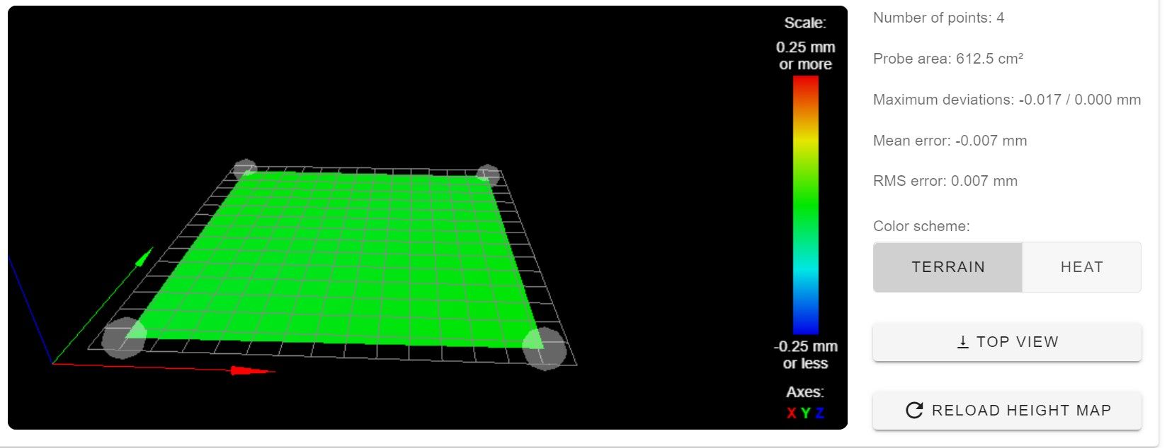
500x500x6mm glass plate - How to interpret height map
-
So, this is a new height map of the glass plate (resting on the original aluminium), and my "corners" are 50mm in from each edge of the build plate, i.e. each of those corner points in the plot are inset 50x50 compared to the edge of the glass.
-
can you post your bed.g and your config.g?
-
It's flat, but tilted. Time to level the bed.
https://duet3d.dozuki.com/Guide/Ender+3+Pro+and+Duet+Maestro+Guide+Part+4:+Calibration/40#s156
-
@Phaedrux said in 500x500x6mm glass plate - How to interpret height map:
It's flat, but tilted. Time to level the bed.
he did, manually and using G32
-
") Plus the printer in that doco doesn't look much like a Core XY triple Z screw machine #diversity haha
Plus the printer in that doco doesn't look much like a Core XY triple Z screw machine #diversity hahabed.g and config.g below, I also added my homeall.g as that's usually what else would be involved in my initial sequence.
BED.G
; bed.g
; called to perform automatic bed compensation via G32
;
; generated by RepRapFirmware Configuration Tool v3.1.4 on Tue Oct 20 2020 23:24:44 GMT+0800 (Australian Western Standard Time)M561 ; clear bed transform
M913 X40 Y40 ; drop motor currentsG30 P0 X450 Y65 Z-99999 F1000 ; probe near front-right leadscrew
G30 P1 X50 Y65 Z-99999 F1000 ; probe near front-left leadscrew
G30 P2 X250 Y400 Z-99999 F1000 S3 ; probe near rear leadscrew and calibrate 3 motorsM913 X100 Y100 ; reset motor currents
G29 S1 ; load height map
CONFIG.G
; Configuration file for Duet 3 (firmware version 3)
; executed by the firmware on start-up
;
; generated by RepRapFirmware Configuration Tool v3.1.4 on Tue Oct 20 2020 23:24:45 GMT+0800 (Australian Western Standard Time); General preferences
G90 ; send absolute coordinates...
M83 ; ...but relative extruder moves
M550 P"Duet 3" ; set printer name
M669 K1 ; select CoreXY mode; SET DIRECTION OF TRAVEL FOR STEPPER MOTORS
; X
M569 P3 S1 ; physical drive 0.3 goes forwards; Y
M569 P4 S1 ; physical drive 0.4 goes forwards; Z has three steppers
M569 P0 S0 ; physical drive 0.0 goes forwards - Front left
M569 P1 S0 ; physical drive 0.1 goes forwards - Front right
M569 P2 S0 ; physical drive 0.2 goes forwards - Rear Center; Extruder
M569 P5 S1 ; physical drive 0.5 goes backwards; MAP STEPPERS TO X Y Z - Z HAS THREE DRIVERS ASSIGNED
M584 Z0:1:2 X3 Y4 E5 ; set driver mapping for XYZ steppersM906 X1600 Y1600 Z1600 E1400 I30 ; set motor currents (mA) and motor idle factor in per cent
M671 X530:-30:250 Y53:53:530 S50 ; Z-screw locations - front right, front left and rear center
M350 X16 Y16 Z16 E16 I1 ; configure microstepping with interpolation
M92 X80.00 Y80.00 Z400.00 E409.00 ; set steps per mm
M566 X900.00 Y900.00 Z12.00 E120.00 ; set maximum instantaneous speed changes (mm/min)
M203 X30000.00 Y30000.00 Z2000.00 E1200.00 ; set maximum speeds (mm/min)
M201 X500.00 Y500.00 Z20.00 E250.00 ; set accelerations (mm/s^2)
M84 S30 ; Set idle timeout; Axis Limits
M208 X0 Y0 Z0 S1 ; set axis minima
M208 X500 Y500 Z500 S0 ; set axis maxima; Endstops
M574 X1 S3 ; configure sensorless endstop for low end on X
M574 Y1 S3 ; configure sensorless endstop for low end on Y
M574 Z1 S2 ; configure Z-probe endstop for low end on Z; Z-Probe
M950 S0 C"io5.out"
M558 P9 C"io5.in" H7 R1 F120 T10000 A3 S0.03 B1 ; set Z probe type to bltouch and the dive height + speeds
G31 P500 X-26 Y0 Z2.28 ; set Z probe trigger value, offset and trigger heightM557 X25:475 Y25:475 S150 ; define mesh grid
; Heaters
M308 S0 P"temp0" Y"thermistor" T100000 B4138 ; configure sensor 0 as thermistor on pin temp0
M950 H0 C"out0" T0 ; create bed heater output on out0 and map it to sensor 0
M307 H0 B0 S1.00 ; disable bang-bang mode for the bed heater and set PWM limit
M140 H0 ; map heated bed to heater 0
M143 H0 S120 ; set temperature limit for heater 0 to 120C
M308 S1 P"temp1" Y"thermistor" T100000 B4138 ; configure sensor 1 as thermistor on pin temp1
M950 H1 C"out1" T1 ; create nozzle heater output on out1 and map it to sensor 1
M307 H1 B0 S1.00 ; disable bang-bang mode for heater and set PWM limit; Fans
M950 F0 C"out7" ; create fan 0 on pin out7 and set its frequency
M106 P0 S0 H-1 C"Part Cooling" ; set fan 0 value. Thermostatic control is OFFM950 F1 C"out8" ; create fan 1 on pin out4 and set its frequency
M106 P1 S1 H1 T45 C"Volcano" ; set fan 1 value. Thermostatic control is ONM950 F2 C"out9" ; create fan 0 on pin out5 and set its frequency
M106 P2 S0 H-1 C"Case 1" ; set fan 2 value. Thermostatic control is OFF; Tools
M563 P0 S"Volcano" D0 H1 F0 ; define tool 0
G10 P0 X0 Y0 Z0 ; set tool 0 axis offsets
G10 P0 R0 S0 ; set initial tool 0 active and standby temperatures to 0CM591 P7 C"io0.in" S1 D0 ; Filament runout sensor
; Miscellaneous
M501 ; load saved parameters from non-volatile memoryHOMEALL.G
M201 X1000 Y1000 ; reduce acceleration on X/Y to stop false triggers
M915 P0:1 S3 R0 F0 H400 ; Sensitivity 4, don’t take action, don’t filter, 400steps/secM574 X1 Y1 S3 ; use stall guard for endstops
G91 ; set relative
G1 H2 Z5 F1200 ; lower the bed;
; X home - using ensorless homing
M913 X40 Y40 Z100 ; drop motor currentsG1 H1 X-550 F6000 ; move until the motor stalls - COARSE HOME
;
; Y home - using sensorless homing
M913 X40 Y40 Z100 ; drop motor currentsG1 H1 Y-550 F6000 ; move until the motor stalls - COARSE HOME
;
; Z home - using Z Probe
G90 ; absolute positioning
G1 X250 Y250 F10000 ; go to first probe point
G30 ; home Z by probing the bedM913 X100 Y100 Z100 ; motor currents back to 100%
M201 X3000 Y3000 ; accel back to original -
@vistalert said in 500x500x6mm glass plate - How to interpret height map:
M561 ; clear bed transform
M913 X40 Y40 ; drop motor currentswhy are you dropping motor currents?
G30 P0 X450 Y65 Z-99999 F1000 ; probe near front-right leadscrew
G30 P1 X50 Y65 Z-99999 F1000 ; probe near front-left leadscrew
G30 P2 X250 Y400 Z-99999 F1000 S3 ; probe near rear leadscrew and calibrate 3 motors
M913 X100 Y100 ; reset motor currentsG29 S1 ; load height map
this should not be here
-
Motor currents:
I've been using sensorless homing pending the completion of installing the mechanical endstops, so dropping the currents just helps me avoid any loud thumps if the head/bed runs into something.
G29 S1 - will delete this
-
but you are not using sensorless homing for the z. so why are you dropping the current when probing the bed?
-
@Veti ...remember when the BL Touch logic level was wrong and the bed would hit the nozzle? It's just a safety measure. Are you thinking it might be skipping on the way up/down? I'd not considered that.
-
no you are just dropping the x and y current. this makes no sense.
-
@Veti yeah I see what you mean. That's all gone now - I've just finished fitting mechanical end stops for X and Y. So I can start testing again tomorrow.
Thanks for the input once again.
-
@vistalert said in 500x500x6mm glass plate - How to interpret height map:
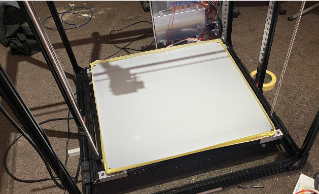
Just to extend the discussion slightly. The glass is sat on my old aluminium plate. What are my next best actions. Should I?
-
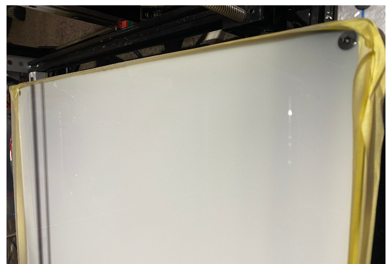
Bond the 6mm glass to the 4mm aluminium plate? The plate is deformed. To achieve good thermal conduction from the heater pad into the glass, I'd have to bond them, as otherwise there would be "pockets of air" underneath the glass, where the plate drifts away from the glass due to a lack of flatness.
-
Or should I (can I) remove the heater pad from the aluminium plate, and
a) apply it to a thinner aluminium plate, which in turn would be bonded to the glass
(being thinner it would be flatter and can easily be bonded and have weights
applied until the adhesive sets)
b) apply the heater pad straight to the glass
This is a classic conundrum...
-
Attaching the glass to the aluminium:
Glass basically won't expand at all, at the temps you will run. The aluminium however will expand. Depending on what you use to glue the glass down, you can end up actually breaking the glass when you heat it up. And if it doesn't break, there's a good chance the whole assembly will warp.
And getting the sandwich to be flat to begin with is harder than you think. Unless you have a granite reference surface (and even then...) -
Depends on the adhesive. You might be able to get it off, but you'll probably ruin the adhesive in the process... they are not designed to be removed.
a) A thin sheet would still have some value as a heat spreader, and reduce the issues related to differential thermal expansion (because it will not be able to exert as much force).
b) No issues with thermal expansion, but less uniform heat distribution. Plus if you break the glass...
Not helpful I know, but my eventual decision was to just not use glass. Its too fragile and too poor a thermal conductor.
Aluminium base, with magnets, steel flex plate with the polymer top-coat of your choice.Isolate, substitute, verify.
-
-
This is just my two cents, but what I ended up doing in a very similar situation was I bought a <10$ silicone baking sheet and put it between the glass and the aluminum. This fills any air pockets and tends to let the glass float flat - or at least that's what I believe. It adds a couple of minutes to the heat-up time but I've used an IR temperature sensor to check bed temperatures and it is remarkably uniform.
I also have 3 Z axis motors.
I set the bed up about a week ago (using the bed-screws that have springs to straighten it).
Before the day starts I do a sanity test 4-point scan with my IR sensor. I've done maybe a dozen or so prints since then and after each print I manually take the glass bed off the sheet, remove the print, then replace the bed. The baking sheet is very non-slip and nothing moves during printing.
Here was this morning's scan.
-
@theruttmeister said in 500x500x6mm glass plate - How to interpret height map:
Aluminium base, with magnets, steel flex plate with the polymer top-coat of your choice.
Might be getting off topic here, but how is your base arranged? I'm thinking of implementing a magnetic-attached steel sheet, but my current bed arrangement is an aluminium plate with silicone bed heater heater bonded on the bottom and I'm not sure how to work the magnetic into that.
One option is an adhesive magnetic sheet on the top of the aluminium, but I basically don't trust they will stay magnetic long at 90C (or hotter - I occasionally print ASA).
-
@achrn
Before the heater was attached, 25 ~6mm holes were drilled through the plate (which is 305x305x6mm).
25 6mm (or it could have been 1/4", I don't recall) neodymium magnets were inserted into the plate (which was on a flat surface, so the magnets ended up flush). 2 part epoxy was added to the holes (this is the hardest part, as you need the right kind of epoxy and it needs to get between the magnet and the walls of the hole)... Although I last did this a couple of years ago, so it might have been superglue... There were certainly issues getting the glue right.
And the hole must be bigger than the magnets, neodymium magnets are brittle and cannot be press-fitted.The holes are in a grid, the outer edges being about ~12mm in from the edge. The magnets are D6mm L5mm
The steel plate is from a buildtac flexplate system (their magnet base kept melting).I don't print in anything too crazy these days, but the curie temp of a good neodymium magnet should be well over 200C, at least according to wikipedia. So you should be good even if you need to print in unreasonable materials.
Full credit to Nophead, who I just copied.
Isolate, substitute, verify.
-
@theruttmeister @achrn I've ended up ripping off the stick on magnetic layer that was applied to my 4mm plate. I had originally intended to have a magnetic PEI sheet. So this whole hassle of the warped 4mm plate is having some big knock on effects.
I tried to put glass straight on top of the 4mm plate, but it rocks around when the aluminium is heated so I think I'm going to use a variation of the silicon idea, whilst I also source a 7mm / 8mm replacement plate.
My idea for the silicon is I have some Liquid Silicon Rubber which is intended for casting moulds. So I hope that what I can do is skim a layer of that over the aluminium and it will fill out the voids. I'm still anxious that it will deform when heated though.
On the whole I think it's gonna cost me a new aluminium bad and a new bed heater as I don't know if I have any chance of getting the heater off of the 4mm plate.
-
Well here goes nothing - laid a layer of LSR over it, spread it like you would if you were applying tile cement to a wall, i.e. with a grooved/slotted flat spreader, seems to have run out pretty flat and to the tops of the levelling screws. Will give it the rest of the day to cure then put the glass back on top and see what happens.
-
I wouldn't have gone down that route myself... silicone rubber is a good insulator, so great for filling those gaps and absorbing any expansion, but its going to take an age for the glass to heat up (although to be fair, the glass is already a good insulator, so the difference might not be that big).
I used to think glass was the best possible bed surface, but I learnt:
- VERY VERY flat glass isn't that expensive or hard to get your hands on (if you are an OEM at least). BUT, its very fragile. PET tends to eat chunks out of it.
- Toughened glass is NEVER flat. Not even close.
- If you are heating it, you need to use borofloat anyway... and that is still fragile and is also not very flat.
I got sick of the cost of replacing broken glass. Hence the aluminium and steel. Well, that and at the time the best self leveling option was an inductive sensor. You don't want to know how much magnetic glass costs...
And provided you only have a very thin layer of silicone, it won't be that hard to remove. Just use a very thin steel wire to cut it from the side. Trying to lever the two pieces apart will just smash the glass.
-
@theruttmeister said in 500x500x6mm glass plate - How to interpret height map:
silicone rubber is a good insulator
Yes, but better than air. Would need to know if there are more air gaps than contact spots to see how it comes out in the wash, but a thin layer may not be too bad really.
-
@Phaedrux said in 500x500x6mm glass plate - How to interpret height map:
@theruttmeister said in 500x500x6mm glass plate - How to interpret height map:
silicone rubber is a good insulator
Yes, but better than air.
ahem
yes, but a better conductor than air.
")
True.
And you could use copper filled silicone. I seem to recall that being a thing. Marginally better thermal conduction iirc.