I guess I have too much time on my hands because I'm designing and building a CNC pendant. I have three Duet3d-based systems in-house (a CNC, a 3d printer, a milling machine) and I really need a portable pendant.
Now that it's nearly finished I thought it might be time for some feedback ")
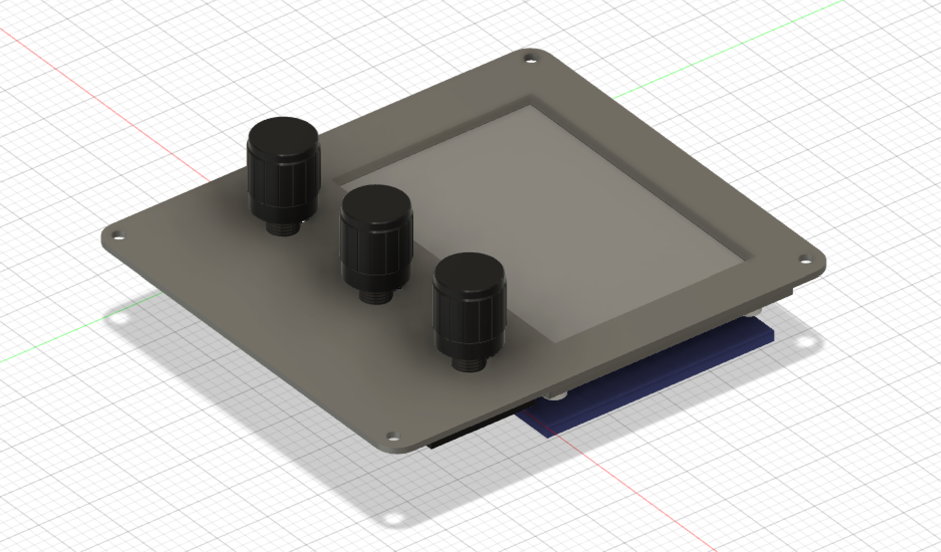
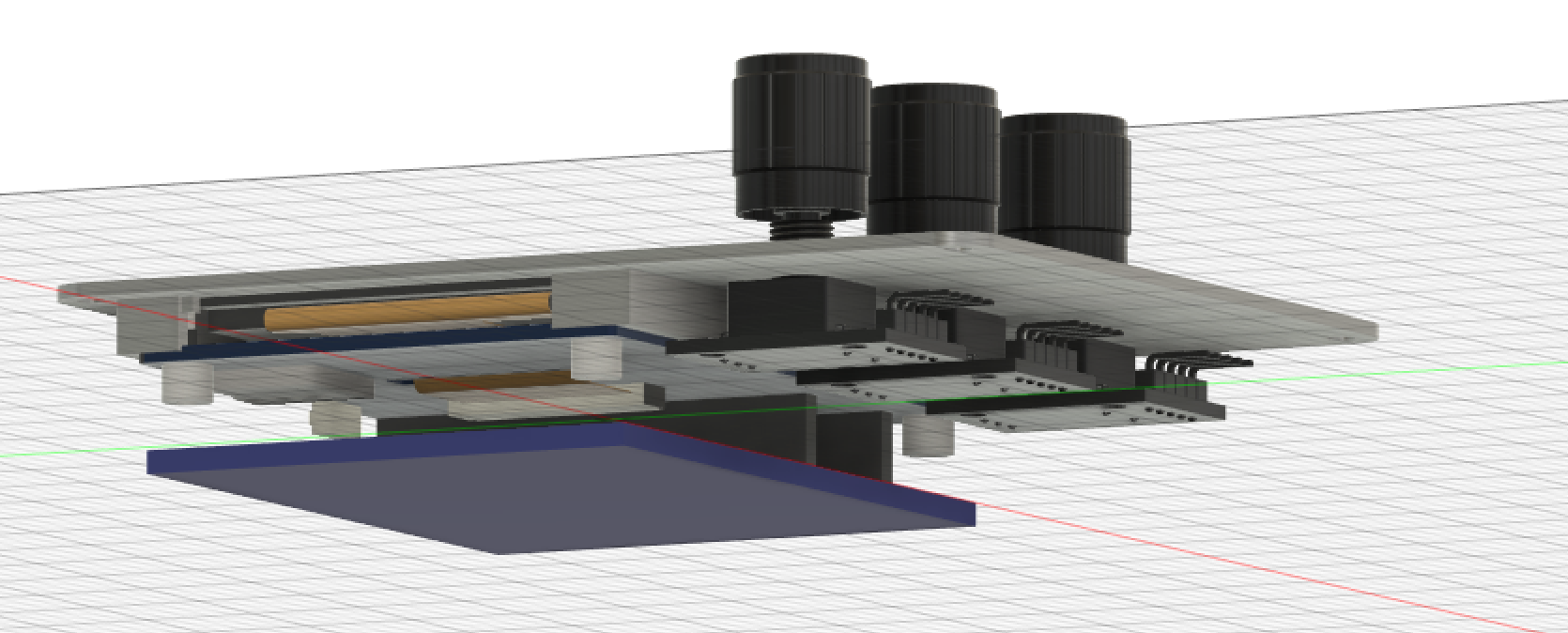
Here's a quick view of what I'm building.
The case is 3d printed so pretty malleable. Each grid box is 1/2" (sorry not-metric) so the case is about 3.5"x4"x2".
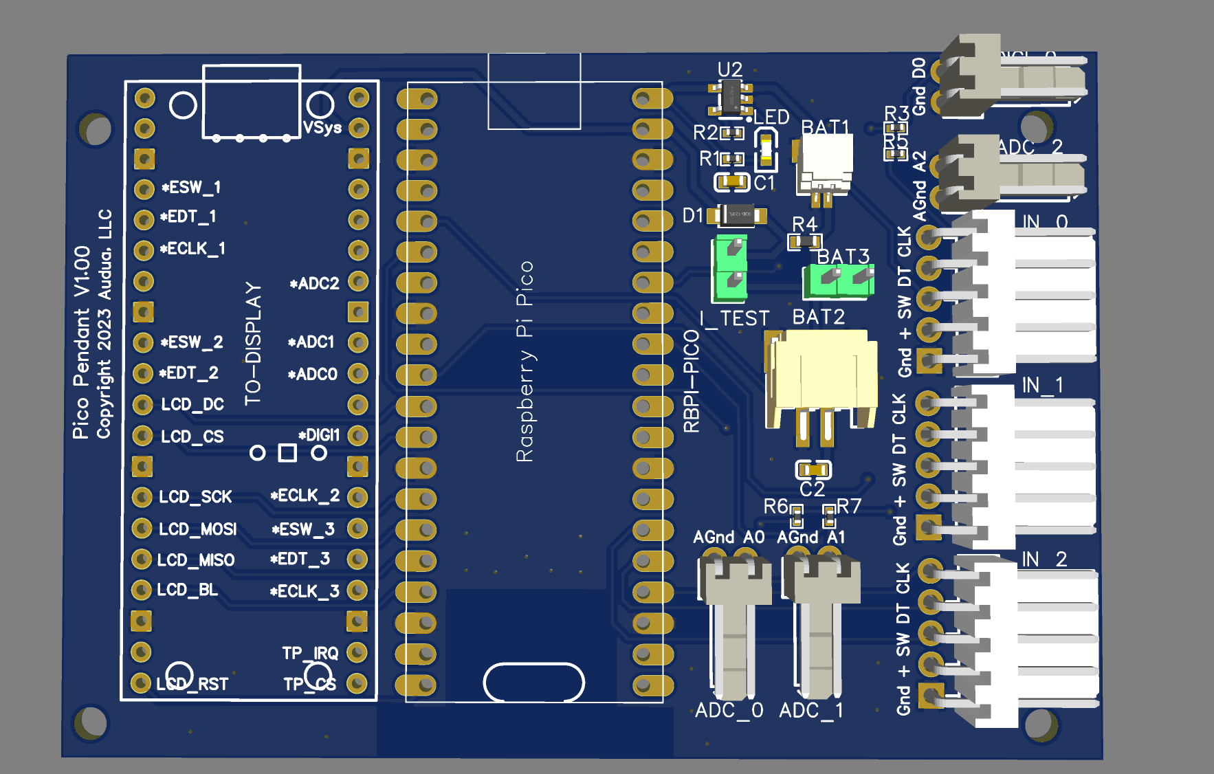
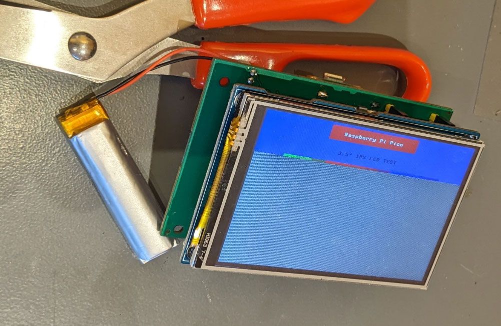
Here's a quick view of the board (V1.00).
The board is designed to fit onto this 3.5" touchscreen display -> https://www.waveshare.com/wiki/Pico-ResTouch-LCD-3.5 but it should work with most any display, just not as well-mounted. The carrier board holes fit the display.
The WaveShare display has a socket for a Raspberry Pi Pico. The carrier board has two Pico 'sockets'. The center socket is to flush-mount or pin-mount a Raspberry Pi Pico W, the other just has pins mounted for the display board.
There is a LiPo battery charger and voltage source circuit, as well as 7 input sockets: 1 digital input, 3 analog inputs (for potentiometers or ladder switches), and 3 multi-inputs for standard arduino rotary encoders or just usable as 3 digital i/o's per input. There are three different optional battery connectors in parallel - a 1mm JST, a 2mm JST, and a molex 2-pin. In addition there's a primitive current test pin.
The sample image of the pendant shows it with three rotary encoders - which I think will be my first attempt. By default they'll do X,Y,Z positioning.
I build these at JLCPCB in China, where the cost per board is tiny (<$5) but the setup+mail costs are close to $40/order. The first run was 5 boards which may be the last run if they work.
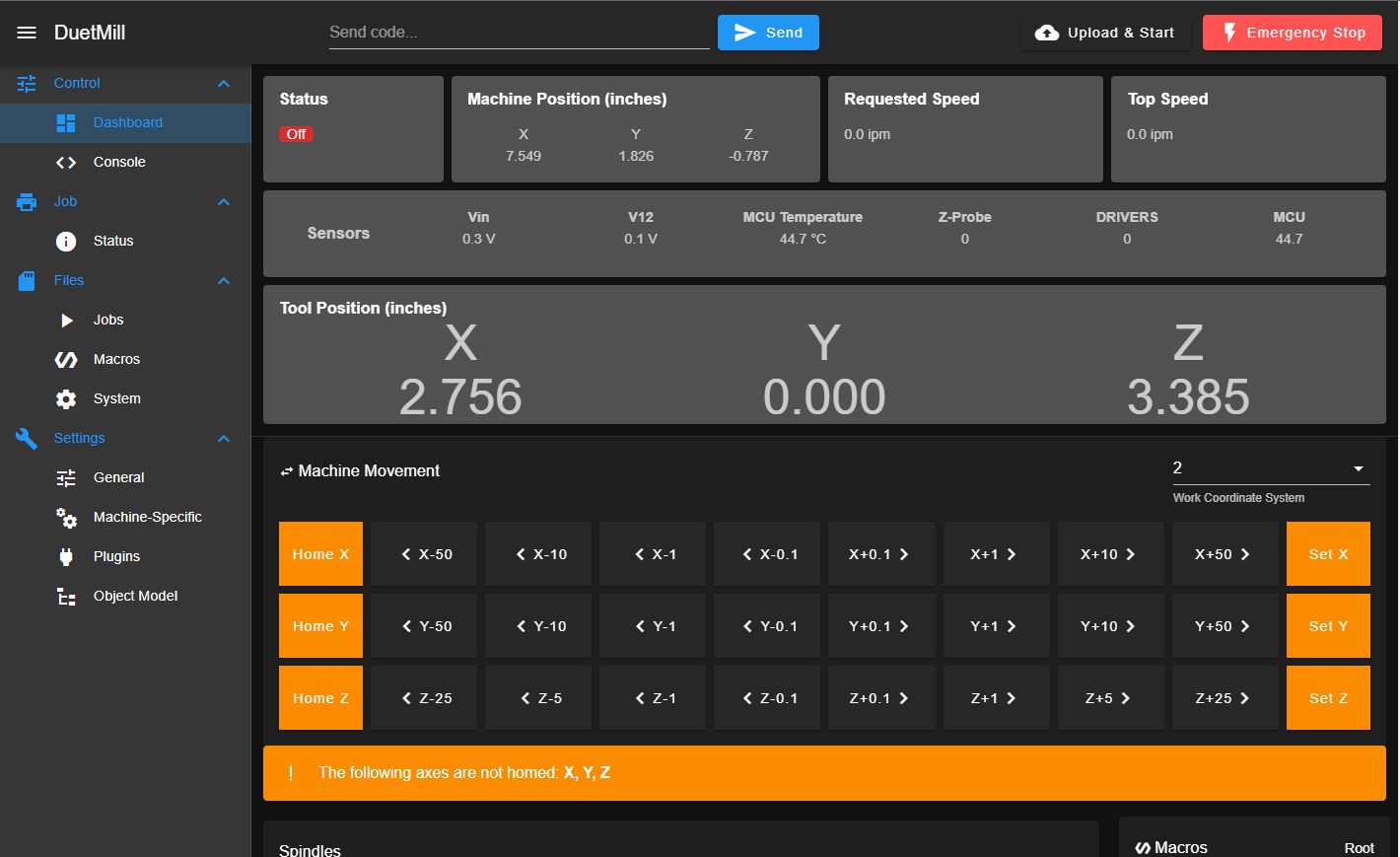
For software I'm planning to use MicroPython and have it talk to the Duet boards via the REST api. If this fails (so far it looks good) I'll switch to C++.
Mark
 That's a useful feature for testing but still...