Robot Type 1 45 cm - belt gear - direct drive - R0
-
#1 of 15 Overview
The Type 1 robot printer has the following properties:
- easy to be built in mind: with a few tools like boring machine, hack or band saw, some measuring tools it is possible to build the robot 3D printer
- print area about 45 cm in every direction
- belt gear based
- direct drive extruder
- R0 mode, i. e. Axis 4 has an actuator, needing 5+1 stepper drivers in total
- no rail
- precision is expected to be middle
Duet 3 has enough drivers (6), Duet 2 needs one additional driver with Duex or as external driver, Duet 3 Mini 5+ needs one additional driver with a 3HC, 1LC, 1XD or similar board. I have no Maestro, so I could not test whether performance is sufficient, and I have no knowledge about which driver extensions are needed.
The robot project is accompanied by the following links and documents:
- main discussion thread https://forum.duet3d.com/topic/17421/robotic-kinematics
- configuration documentation: https://duet3d.dozuki.com/Wiki/Configuring_RepRapFirmware_for_a_FiveAxisRobot?revisionid=HEAD
- homing documentation: https://duet3d.dozuki.com/Wiki/Homing_for_a_FiveAxisRobot
#2 to #15 target specific topics (work in process).
-
#2 Weights, Torques, Stepper dimensioning
Belt based gears have no brakes like harmonic, planetary or cycloidal drives. The arms would fall down when power off. The goal is to balance the weights of the arms and axes so that the arms are in balance even when powered off. The steppers have detent torque, which is holding torque when they are powered off. The inbalance must be smaller than the detent torque. Detent Torque is stepper spedific, but a typical value is 2 Ncm for a Nema 17 and 12 Ncm for a Nema 23. The weight is best planned from end to begin, beginning with axis 5's weight.
The torques are calculated by adding up all elements of a specific axis with their distances from the axis. A N (newton) is about 100 g, the distance is in m. E. g. 500 g Nema 17 stepper 20 cm away from the axis is 5 N * 0.2 m = 1 Nm = 100 Ncm. Summing up left and right results in the total torque. Weights of or vertical above or below the axis do not count for torque calculation (0 distance). A Nema 17 stepper with detent torque of 2 Ncm and a gear with ratio 1:24 can take an inbalance of 48 Ncm up- or downward. The torque calculations is for horizontal elements. Rotating dimishes the torques (inclined plane), but the same factor on both sides.
Arm 4 is vertical, so there is no static torque if Axis 5 is balanced.
A higher weight has a negative effect on acceleration and speed, even if the torque is balanced.
Current stepper dimensioning is
- Extruder: Nema 17 short with 1:3 gear (1 stage)
- Axis 5: Nema 11 with 1:9 belt gear (2 stage)
- Axis 4: Nema 17 with 1:24 belt gear (2 stage)
- Axis 3: Nema 17 with 1:24 belt gear (2 stage)
- Axis 2: Nema 23 with 1:40 belt gear (2 stage)
- Axis 1: Nema 17 with 1:40 belt gear (2 stage)
For a detailed weight and torque calculation see in step #14. But roughly Axis 5 is balanced: 550 g, from axis 4 total weight (including Axis 5): 790 g, from Axis 3: 2.3 kg, from Axis 2: 5 kg and the total robot weight without foundation and print bed about 6 kg.
-
#3 Axis 5, Extruder, Hotend
-
4/11 axes and arms 2, 3, 4
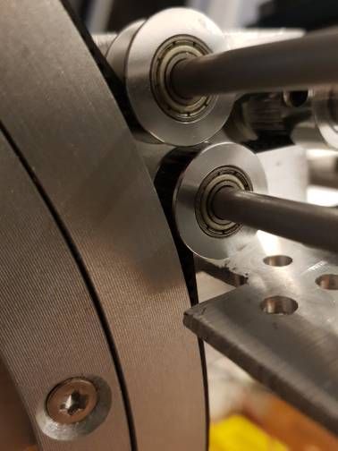
Axis 2 to 4 are assembled by
- the arms are connected by shafts and F688 ball bearings in 16 mm holes
- to give additional sideways stability and function as gear, the arms are connected by rotation plates
- the arms are constructed from aluminium 20x10x2 hollow square tubes
- the holes inside the arms have raster 1 cm distance each, an exception are the holes for the rotation plates. Holes of 4.5 are for M4 screws, holes of 16 mm are holding the F688 ball bearings
- arm 2 length is 27 cm, arm 3 is 23 cm, arm 4 is currently 15 cm. The aluminium square tubes must be longer to take the steppers on the other sides of the axes: tube 2 has 60 cm length, tube 3 has 60 cm, tube 4 has 20 cm, arm 5 is only virtual. When using Nema 17 at axis 2 is used, a longer tube 2 may be useful for for counterweight torque.
-
#5 Axis 1, plate calibration, fundament, print bed
-
#6 Tools, Hole Processing
-
7/11 Rotation Plates
Rotation plates are big ball bearings from aluminium material with steel balls.
Plate for Axis 1 has 250 mm diameter, Axis 2 250 mm also, Axis 3 and 4 120 mm each. Weight of 250 mm is 450 g, of 120 mm is 180 g each.As example plate for Axis 4:
Building:
- connecting two arms each by 8 mm shaft, connecting to arm by 16 mm hole and F688 ball bearing
- pressing inner and outer ring of plate by spring in middle on shaft
- arms connected to plate at two holes in plate each, countersink screws
- Axis 4 special connection of arm 4 (arm 4 is a 8 mm shaft)
Arm-plate and Arm-arm connection precision (hole positions) is important for the rotation to be smooth.
In the image, one arm has only a 8 mm hole for the shaft. This will be changed to 16 mm with F688 in next iteration.
-
#8 Gearboxes
Guidelines for construction
- gear ratio 1/2 (20/40 teeth) or 1/3 (20/60 teeth) * ratio 20 to big wheel
- gearbox from aluminium U profile 40x40x40x2 with length 50 mm (gear 5 longer)
- teethless pulleys are on 5 mm aluminium shaft
- teethes geared pulleys are on 8 mm aluminium shaft, at aluminium case with F688 ball bearings
- screws are M4 all
Gear 1:
Gear 1 will be reworked.
and
Gear 1 is the most complex one, because the 20/60 is belt is routed under the rotation plate to the side under the plate.
The box has size 40x40x40x2 with length about 5 cm. The gear is still 1:3, but will change in next iteration to 1:2 to give a total of 1:40.
Gear 2:
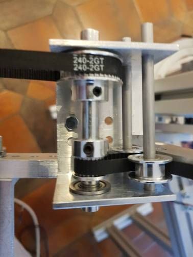
Teethless pulleys near the rotation plate:
The gear is connected to Nema 23. For Nema 23 to be placed in the middle of the arm for better balance, the gearbox has size 40x60x40x2 with length 5 cm.
This version is how I like it:
- the two teethless pulleay near rotation plate have minimum distance to it
- minimum 19 mm distance of teethless pulleys
- minimum distance between teethless 5 mm pulley shaft to 8 mm shaft is 25 mm.
- the 20 and 40 pulleys are on a 8 mm shaft, connected to the gearbox with a F688 and in future with 8x12x0.5 washer between
Gears 3, 4:
- based on 40x40x2 U profile with 50 mm length
- teethless pulleys are on 5 mm shaft
- 20/60 pulley gear is on 8 mm shaft
5 mm screws will be replaced by shaft in next iteration.
Gear 5:
The gearbox is from 40x40x40x2 with length 13 cm. Not finished yet, right will be connected the Extruder. An additional tensioner for the lower 20/60 gear is needed. Size of right Arm 4 axis to left is 10 cm, right will be about 5 cm for Extruder. I let enough room on top to install Nema 17 if necessary. Length from top to bottom is maximum 10 cm, right Extruder + heatbreak + hotend will be about 12 cm. The assembly allows free rotation of axis 5 under arm 3 (free is relative, because wiring and filament will hinder it). Placing the steppers as near to arm 4 as possible for low torque. I'll try to balance arm 4 when finished building.
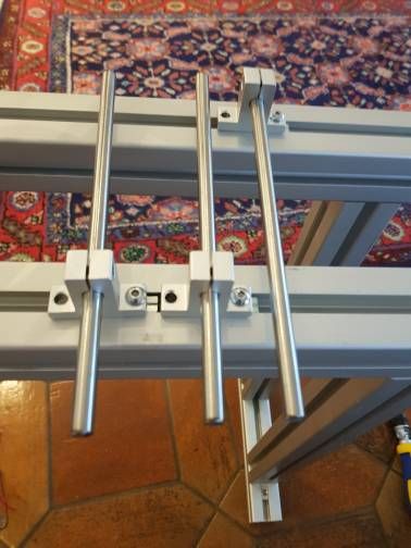
Belt and distance measuring
To find closed belts which fit well and then measure the distances of the pulleys, I used a little "tool":
-
9/11 Belts, Tensioning
The belts on the rotation plate to the gearbox are open belts, fixed on the rotation plate:
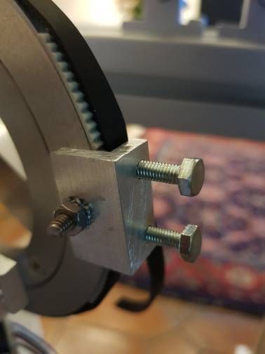
Aluminium L profile 4 mm or more. M4 to fix it at the plate. Two M4 threads with M4 screws on top. GT2 short belt (here steel belt) to make sure belts do not slip. I have no good belt tensioning at the moment.
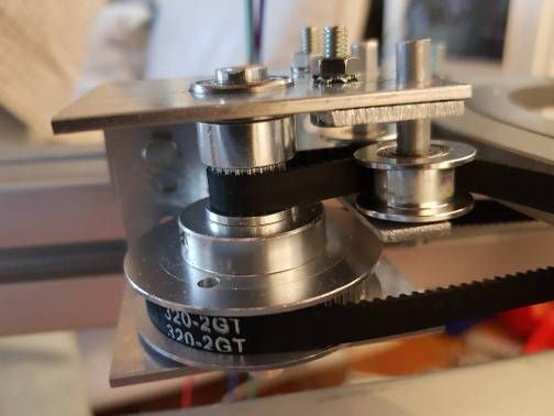
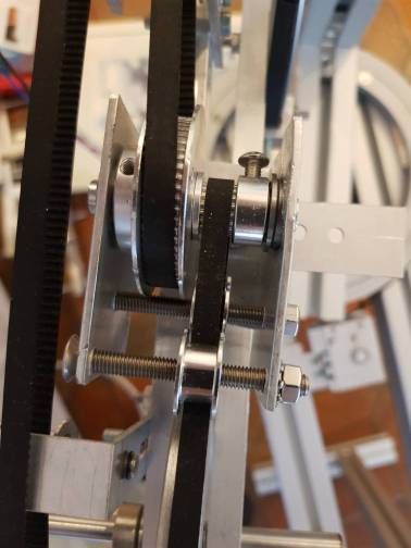
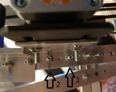
The belts between gearbox and stepper are closed belts. The belt tension is handled by:
First use screw 1 to place the stepper in a distance so belt has a bit tension. Then screw 2 by rotating the stepper so that belt has good tension. The screw 2 has a slot as counterpart instead of a hole:
Second the already good tensioned belt with higher tension:
The tensioner is at the middle between gearbox and stepper. Aluminium 2 mm is too weak, 3 to 5 mm needed. The connector between arm and stepper holder should be 3 to 5 mm also, instead of 2 mm, which bends.
Closed Belt lengths:
- Gearbox 1: 20/40, distance xx mm, belt 350 mm (175 teeth).
- Gearbox 2: 20/40, distance 90 mm, belt 240 mm (120 teeth).
- Gearbox 3: 20/60, distance 180 mm, belt 450 mm (225 teeth).
- Gearbox 4: 20/60, distance about 340 mm, belt 760 mm (380 teeth)
- Gearbox 5 first at stepper: 20/60, distance 47.8 mm, belt 180 (90 teeth).
- Gearbox 5 second stage: 20/60. distance 78.5 mm, belt 240 (120 teeth).
-
10/11 Endstops, Calibration
-
11/11 Electronics, Duet Configuration
-
#12 precision analysis
-
#13 improvements
-
#14 BOM lists, weight calculation
-
#15 images of printed things
-
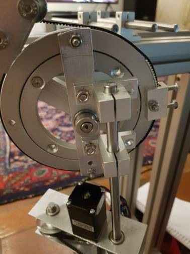
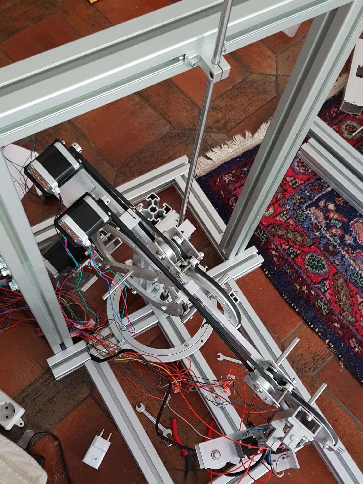
I want to give an update of my robotics development:
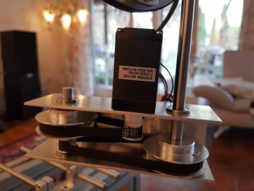
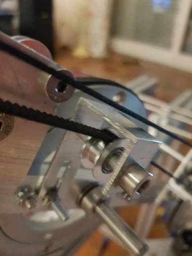
The belt gear and hotend construction is working quite good:

The Nema 11 is strong enough for the 1:9 gear and the belt tensioner allows precise rotation. Left and right side are nearly balanced, so axis 4 needs only little force if it stays vertically (maybe using Nema 11 in the future also).
The middle (axis 3 and 4) are working good also, a belt tensioner is important. The rotations produce little vibrations:

The problem right now is the axis 1 and 2. Fast rotation result in big vibrations. I have to improve the construction:

The belt gears are working very good, but high speed results in vibrations of the whole construction. My interpretation is, the vibrations are due to cantilevered constructions, eg arms fixed at one end, but not the other. Or an axis with only one ball bearing. I'll try to improve it.
Next steps:
- build a stable construction of axis 1 and 2, probably by fixing every axis at two points (ie two ball bearings) and parallel arms instead of one. The big aluminium rings (esp. axis 1) are not trustworthy enough, they have too much play, I need to support them with additional axis in the middle like I made it at axis 2, 3 and 4
- one important topic is how to route the wirings, especially the long ones from the hotend. Axis 5 can rotate more than 360 degree, the cables must be able to rotate freely.
-
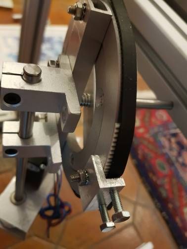
I've stabilized axis1 and 2 now with this construction:
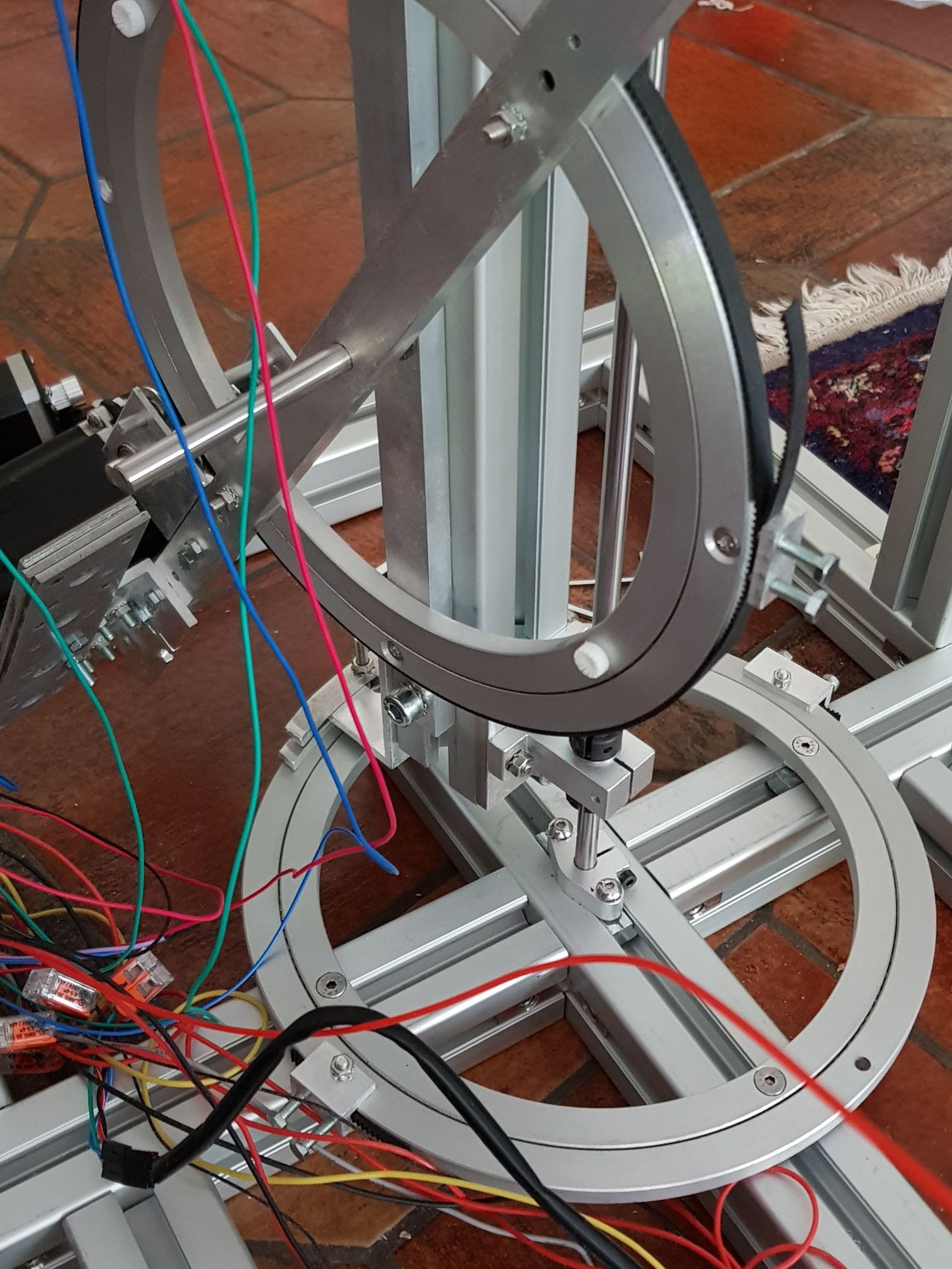
I've separated the rotation constraint from driving the axis: axis 1 rotates around the vertical shaft which is fixed top and bottom. The driving is done by the horizontal 25 cm rotation plate. The vertical shaft fixes the rotation (and could be replaced later by a 20 or 30 mm shaft, currently it is 8 mm), the horizontal plate needs not to be as precise as before.
The height of the frame is 80 cm now. I'll place the axis 1 actuator behind the construction, so the bed space remains free.
I prepare the hotend to use a toolboard to reduce the wiring mess.
Maybe I'll second every arm with a parallel arm strut to stabilize the horizontal axes 2, 3 and 4.
Next steps:
- reinforce frame
- install axis 1 actuator, left of construction
- install endstops
- route the wiring
- place bed and be creative how to calibrate it. I plan to use 2 actuators for leveling, probably with differential screws
- minor improvements for belt tension
The aluminium plates (big wheels) are not as precise as I hoped. I will change the construction to separate axis as hinge from the rotation force of the plates for the axes 2, 3 and 4 also, like I did for axis 1. But this is a major reconstruction, I will test firmware first with the current construction. When the alu plates have only the task of driving the rotation, I'll try to replace them by 3d printed parts. This will save weight.
-
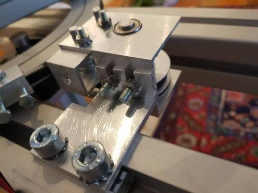
The connection between the alu extrusion and shaft is built by:
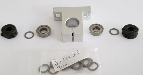
The left black part is very nice, two halfes, can be assembled/disassambled without disassambly of the construction. The washers hinder contact with rotating parts of ball bearing. Ball bearing is F688 (inner 8, outer 16 mm), in middle is SH16/SK16.
-
@JoergS5
I read this for the first time and found some typo? in #2 post.Detent Torque is stepper spedific, but a typical value is 2 Nm for a Nema 17 and 12 Nm for a Nema 23.Isn't it Ncm, not Nm? I check my datasheets again.
Hope your arms are in balance, nevertheless? -
@o_lampe thank you, you're right! I'll correct it. Nm would be nice (but a slow motor).
I am currently rebuilding arm 2, working forward to the hotend. I think stability of frame, arms and hinges is key to precision - but this will be true for every printer type.
The frame around the robot is ugly and dangerous (sometimes the robot touches the frame), I'll try using a 25 mm shaft, fixed at the bottom at two points. The 8 mm shaft bends when the axis rotates.