Confusion on M558 for Duet Maestro with RRF3
-
Hi there. I've found conflicting information regarding the proper setting for M558 on a Duet Maestro with RRF3.
Here, dc42 says that it should be P1: https://forum.duet3d.com/topic/7208/ir-probe-and-duet-maestro?_=1607816200149
On his blog, he says that for RRF3, it should be P8: https://miscsolutions.wordpress.com/mini-height-sensor-board/
Here, it doesn't explicitly say Maestro, but it says either P1 or P8: https://duet3d.dozuki.com/Wiki/Connecting_a_Z_probe#Section_Connecting_different_types_of_Z_probe
If I understand the documentation for M558 here: https://duet3d.dozuki.com/Wiki/Gcode#Section_M558_in_RepRapFirmware_Num_3 the numbers have not changed in RRF3. So why has it gone from being an analog sensor in RRF2 (P1) to a digital one in RRF3 (P8)?
What is the proper setting?
-
It can be either. Though I think digital mode is preferred and behaves quicker. When used on a tool board for instance it must be P8 and the analog signal can't be used at all.
Best to use P8.
-
Thanks for that. It's odd though - my sensor always reports 0 with P8. (It reports 3-4 with P1) When it turns on, it blinks once, waits a second, then blinks four more times, which I believe is it entering analog mode?
I saw that another user had the same issue: https://forum.duet3d.com/topic/19864/duet-ir-sensor-stopped-working
I haven't checked the voltages yet on the test pads as pointed out in that thread, but I have confirmed that the wiring is correct.
-
If you want to use the IR sensor in digital mode with a Duet WiFi/Ethernet or Maestro, you will need to enable the pullup resistor on the Z probe input, by using ^ at the start of the pin name.
-
Is that required for P1 or P8?
-
P8 is digital mode.
-
Great, now I see the expected two blinks, however it's still reporting 0 - I guess I'll have to look at the board more closely. It's brand-new, so I'm a bit confused as to why it isn't working properly.
Aside, when I read the documentation, if it says Duet 2, could I assume that it also means the Maestro as well if not specified otherwise? For instance, the documentation on M558 says: "Enable pullup resistor with ^ if using Duet 2, running RRF3, using the Z probe input pin, and the probe type is a switch or BLTouch." I passed over this because it didn't mention the Maestro and I didn't believe the sensor would be designated as a switch because it outputs a distance. (Or is this only in analog mode?)
@dc42 , on your webpage you say "About 4 seconds after power is applied, the LED on the sensor should flash twice, indicating that the board has started in digital output mode." Perhaps you should add that you must enable the pull-up to enter that mode?
-
I've checked the voltages, and they seem to be the same as those provided by fotomas here: https://forum.duet3d.com/topic/19864/duet-ir-sensor-stopped-working
The only difference is that when I probe the point next to R1 the LED starts flashing rapidly:
-
I have confirmed that the IR emitters are active.
Is there anything else I can do to try and diagnose the issue? The only thing I can think of is trying to plug it into an Arduino and see if I can get any data from it directly, however given the fact that it gets power and can sense whether it is in digital or analog mode would imply that the connections are correct.
I was able to get data from it once, but haven't been able to get anything since - and I haven't changed any of the wiring or configuration of the board. It is connected to Z_PROBE_IN, GND and 3.3V on the Z Probe header.
The following is the contents of my
config.g:; General preferences G90 ; send absolute coordinates... M83 ; ...but relative extruder moves M550 P"Printer" ; set printer name ; Network M551 P"redacted" ; set password M552 P0.0.0.0 S1 ; enable network and acquire dynamic address via DHCP M586 P0 S1 ; enable HTTP M586 P1 S0 ; disable FTP M586 P2 S0 ; disable Telnet ; Drives M569 P0 S1 ; physical drive 0 goes forwards M569 P1 S1 ; physical drive 1 goes forwards M569 P2 S1 ; physical drive 2 goes forwards M569 P3 S1 ; physical drive 3 goes forwards M584 X0 Y1 Z2 E3 ; set drive mapping M350 X128 Y128 E64 I0 ; configure microstepping without interpolation M350 Z16 I1 ; configure microstepping with interpolation M92 X711.00 Y711.00 Z400.00 E400.00 ; set steps per mm M566 X900.00 Y900.00 Z12.00 E120.00 ; set maximum instantaneous speed changes (mm/min) M203 X6000.00 Y6000.00 Z360.00 E1200.00 ; set maximum speeds (mm/min) M201 X500.00 Y500.00 Z50.00 E250.00 ; set accelerations (mm/s^2) M906 X800 Y800 Z800 E800 I30 ; set motor currents (mA) and motor idle factor in per cent M84 S30 ; Set idle timeout ; Axis Limits M208 X-20 Y0 Z0 S1 ; set axis minima M208 X275 Y150 Z150 S0 ; set axis maxima ; Endstops M574 X2 S1 P"!xstop" ; configure active-high endstop for high end on X via pin !xstop M574 Y2 S1 P"!ystop" ; configure active-high endstop for high end on Y via pin !ystop M574 Z1 S1 P"!zstop" ; configure active-high endstop for low end on Z via pin !zstop ; Z-Probe M558 P8 C"^zprobe.in" H-5 F120 T6000 ; set Z probe type to unmodulated and the dive height + speeds G31 P50 X6.5 Y-35 Z2.5 ; set Z probe trigger value, offset and trigger height M557 X-30:215 Y15:125 S20 ; define mesh grid ; Heaters M140 H-1 ; disable heated bed (overrides default heater mapping) M308 S0 P"spi.cs1" Y"thermocouple-max31856" ; configure sensor 0 as thermocouple via CS pin spi.cs1 M950 H0 C"e0heat" T0 ; create nozzle heater output on e0heat and map it to sensor 0 M307 H0 B0 S1.00 ; disable bang-bang mode for heater and set PWM limit ; Fans M950 F0 C"fan0" Q500 ; create fan 0 on pin fan0 and set its frequency M106 P0 S0 H0 T45 ; set fan 0 value. Thermostatic control is turned on M950 F1 C"fan1" Q500 ; create fan 1 on pin fan1 and set its frequency M106 P1 S0 H-1 ; set fan 1 value. Thermostatic control is turned off M950 F2 C"fan2" Q500 ; create fan 2 on pin fan2 and set its frequency M106 P2 S0 H-1 ; set fan 2 value. Thermostatic control is turned off ; Tools M563 P0 D0 H0 F0:1 ; define tool 0 G10 P0 X0 Y0 Z0 ; set tool 0 axis offsets G10 P0 R0 S0 ; set initial tool 0 active and standby temperatures to 0C ; Custom settings are not defined ; Miscellaneous T0 ; select first toolI'm using RepRapFirmware for Duet 2 Maestro version 3.1.1 running on Duet Maestro 1.0
-
Your config looks fine. The Maestro is a Duet 2 series board.
When you do a probe test with G30 as described here, what happens?
https://duet3d.dozuki.com/Wiki/Test_and_calibrate_the_Z_probe
Does the probe trigger and halt movement?
Your config also shows a Z endstop configured. But what do you have in your homing files to home Z?
-
It does nothing. If I hadn't stopped it, it would have crashed into the bed. Nothing seems to trigger it.
Yes, I still have a Z end stop configured, and the home Z script utilizes it - I have yet to convert it over to using the Z probe due to this issue.
-
@j3d said in Confusion on M558 for Duet Maestro with RRF3:
M558 P8 C"^zprobe.in" H-5 F120 T6000 ; set Z probe type to unmodulated and the dive height + speeds
H-5 is a bit strange.
can you test with M119. If it not shows as triggered and the probe light is on full it might be your wiring.
-
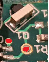
I finally was able to look at the board up-close with a loupe to see what was going on. It looked like the solder underneath the IR receiver had not reflowed completely. Putting a dab of solder at one end seems to have fixed it, and I now have a functioning z probe. Hooray!
Hopefully it remains reliable. I don't have much faith in my soldering skills - however I'm pretty sure that taking a soldering iron to the board terminates the warranty anyways, even if it was a factory defect...

-
Also, my board seems to be missing a component - C1. Is this intentional? @dc42
-
In this case I don't think we'd terminate the warranty unless you really melted the hell out of it.
") Since reflowing the solder point has made it functional it was clearly a defect in manufacturing. If you wish, you can contact your vendor and seek a warranty replacement. Include a link to this thread as authorization. Sorry for the inconvenience.
Since reflowing the solder point has made it functional it was clearly a defect in manufacturing. If you wish, you can contact your vendor and seek a warranty replacement. Include a link to this thread as authorization. Sorry for the inconvenience. -
C1 is intentionally not fitted.
I am glad you found the problem. Soldering the side-looking IR receiver can indeed be a problem because of the unusual location of the pads, and that is the first thing we check when a sensor doesn't respond to a nearby surface.
-
 undefined j3d referenced this topic
-
undefined j3d referenced this topic