Steps per mm keep changing
-
@Veti I have NEMA 23 1.8 Degree 200 step/rev steppers on x,y and z axis. Each stepper drives a 2005 lead screw that moves the gantry in x,y and z axis.
My extruder steppers are NEMA 17 1.8 Degree 200 step/rev steppers. They are mounted with a 7.5mm hob nut to drive 1.73mm filament.
All steppers are directly connected to the stepper drivers on the Duet 3 board. Please let me know if you need more information.
Thanks!
-
@akhilnex said in Steps per mm keep changing:
I have NEMA 23 1.8 Degree 200 step/rev steppers on x,y and z axis. Each stepper drives a 2005 lead screw that moves the gantry in x,y and z axis.
5mm lead with 200 steps would be 640 steps/mm at x16 interpolation.
see https://blog.prusaprinters.org/calculator_3416/
at x32 that would be 1280
at x128 5120see if you did not enable corexy mode by accident.
post your entire config.g
-
@akhilnex said in Steps per mm keep changing:
[Steps per mm] keeps changing
Hello,
I have built my own 3D printer and installed a Duet 3 to control the extruder and axis steppers.My issue is that the error on the distance traveled is variable and keeps changing. So far I have played with different settings (microsteps, current, speed, acceleration, etc.) on the config.g file. The code is shown below:
; Drives
M569 P0.0 S1 ; physical drive 0.0 goes forwards
M569 P0.5 S1 ; physical drive 0.5 goes forwards
M569 P0.4 S1 ; physical drive 0.4 goes forwards
M569 P0.2 S0 ; physical drive 0.2 goes backwards
M569 P0.1 S0 ; physical drive 0.1 goes backwards
M569 P0.3 S0 ; physical drive 0.3 goes backwards
M584 X0.0 Y0.5 Z0.4 E0.2:0.1:0.3 ; set drive mappingThis is odd... I believe that the drives should be in the format 0,1,2,3. Not 0.1,0.2,0.3 etc.
M350 X32 Y128 Z128 I1 ; configure microstepping with interpolation
M350 E128:128:128 I0 ; configure microstepping with interpolation
M92 X6400.00 Y5120.00 Z5120.00 E1207.22:1207.22:1207.22 ; set steps per mmYou say that your axies are all running that same leadscrew... but your settings don't match that. Your Y and Z match what you say, your X is off.
Off the top of my head, 2005 (5mm pitch?) leadscrew, 200 step motor, that should give you an M92 value of 1280. For X,Y and Z. At least if you were using identical microstepping (using the X32 value). Obviously you are not, but they should still be multiples. (And note that running really high microstepping doesn't get you any higher practical resolution, the motors just can't do that. And with interpolation turned on you are already getting the smoothing/noise benefits of x256 microstepping anyway).
I would expect/suggest the following:
M350 X16 Y16 Z16 I1
M92 X640 Y640 Z640 (etc etc)Your acceleration, max speed and motor current all also seem... off. But without knowing more about your setup I can't tell if that's important.
Although the M203 values are just... waaaaay off. If you can't get more than 400mm/min, your machine is very very heavy with tiny tiny motors (and the high microstepping isnt helping there!*). And your E values are off in the other direction (although that's less important).
*If you run really high microstepping you will run into the limits of the CPU of the Duet, there's a limit to how fast it can sent pulses to the drivers.M566 X100.00 Y200.00 Z12.00 E200.00:200.00:200.00 ; set maximum instantaneous speed changes (mm/min)
M203 X400.00 Y400.00 Z18.00 E1200.00:1200.00:1200.00 ; set maximum speeds (mm/min)
M201 X20.00 Y50.00 Z20.00 E50.00:50.00:50.00 ; set accelerations (mm/s^2)
M906 X2500 Y2500 Z2500 E2100:2100:2100 I20 ; set motor currents (mA) and motor idle factor in per cent
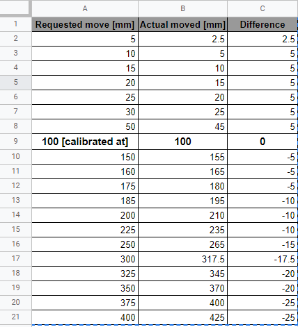
M84 S15 ; Set idle timeoutI tried to change several things by far and all the drives have the same issue for which I have calibrated steps per mm setting to move 10 mm. I recorded the actual moved with respect to requested for one of the extruder motors in the table below:
I am not sure what is causing it and will greatly appreciate your help!
The fact that your results are not consistent makes me think that either your methodology is flawed or is that drive 0.1 vs 1 thing screwing up everything else.
And I realise you weren't asking about machine design... but consider using belts to drive your screws, there's no way any FDM printer can actually make use of the kind of resolution you have and you have sacrificed speed in the process. A 3:1 or 5:1 stage would get you back some of that speed and still keep more resolution that you can see.
-
@theruttmeister said in Steps per mm keep changing:
This is odd... I believe that the drives should be in the format 0,1,2,3. Not 0.1,0.2,0.3 etc.
0.X notation is for the duet 3
-
@Veti said in Steps per mm keep changing:
@theruttmeister said in Steps per mm keep changing:
This is odd... I believe that the drives should be in the format 0,1,2,3. Not 0.1,0.2,0.3 etc.
0.X notation is for the duet 3
Well...
That's... obtuse.I hesitate to ask why on earth that came to be.
-
because you need to address canbus extension. thats the number before the dot.
so ie 121.0 -
Ok, an otherwise incoherent burst of irrational OCD rage averted
")
Someone might want to add that to the wiki though.
Makes no mention of such a thing. And a 3 minute browse of the Duet 3 pages also fails to mention it.
But then I'm one of those people poking around and grumbling about the fact that the SCARA guide is now out of date due to 3.0 changes.
(I know, I know, its a wiki, if I really want it fixed I should go fix it).
I assume that just single digit entries still work the same? 0 or 1 working the same as 0.0 and 0.1?
-
@theruttmeister The Can address for the main board is optional. That is to say, the preceding "0." Is not needed if one only uses a duet 3 main board. If no preceding board number is specified, then the firmware will default to assuming the driver referred to is on the main board. So 0.0 and just 0 would both refer to driver zero on the main board.
Personally, I prefer to always explicitly define values which would otherwise have a default setting - just in case a firmware change altered the default behaviour. Also, because I use 3 expansion boards where the board number is required, it makes config.g more legible if all drivers are referred to using board.driver format. -
@theruttmeister said in Steps per mm keep changing:
Makes no mention of such a thing. And a 3 minute browse of the Duet 3 pages also fails to mention it.
only needed when using expansion boards, so its covered there.
-
@akhilnex said in Steps per mm keep changing:
M350 X32 Y128 Z128 I1 ; configure microstepping with interpolation
M350 E128:128:128 I0 ; configure microstepping with interpolation
M92 X6400.00 Y5120.00 Z5120.00 E1207.22:1207.22:1207.22 ; set steps per mmThe settings don't fit for a 2005 spindle.
The calculation is steps/rotation * microsteps / mm/rotation,
- i.e. 200 * 32 / 5 = 1280 for X
- 200 * 128 / 5 = 5120 for Y and Z
so the M92 for X is wrong.
You can also check the M122 and check for hiccups whether you have lost steps.
Your M203 setting of speed is very low (only about 6 mm/s), this is also strange.But your question was about the extruder:
E128 with I0 without interpolation could mean too high step rate (3 extruders, plus xyz steps), but this would show up in the hiccup reporting of M122. Speed for extruder is maximum 20 mm/s for each extruder, and 1200 steps/mm meaning 24 kHz for every extruder, total 72 kHz. And I would check the current for the Nema 17 steppers, whether 2100 mA is 50 to 80% of the RMS current in the datasheet.I read an intersting article yesterday https://www.geckodrive.com/support/step-motor-basics/accuracy-and-resolution.html about accuracy of steppers. The linearity of steppers of microsteps varies by stepper models. A high microstepping doesn't mean high accuracy. Imho a high ratio gear is a better idea if you want to achieve a high precision of the extruders.
-
Gentlemen,
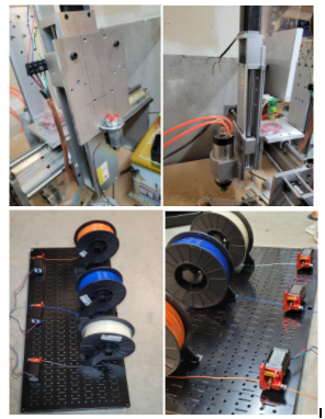
I have now taken a bunch of pictures to clear things up and I apologize for little information past evening. Let me start by explaining the setup in a more detailed manner. The entire CNC/3D printer is an experimental build and I had been running the CNC (X,Y,Z) portion of it originally through another chipset and external drivers for steppers with good results and accuracy.
The reason I changed to Duet 3 was to make a machine that can also 3D print and take advantage of being a CNC mill when needed.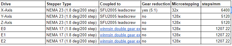
This is based on the reprap configurator tool:
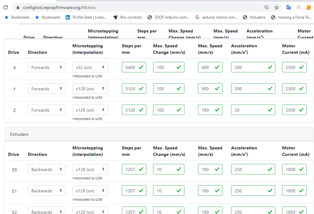
Pictures below show the entire build and the controller with dual Z-axis (that I plan to manually change to based on either I am using CNC mill or 3D print function)
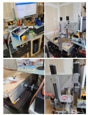
The picture below shows the 3 filaments mounted on a tool board with NEMA 17 motors. The filament runs through a 7.5 mm hob nut and to the hot end (hot end never tested still working on steppers):
What I have tried so far?
-
Changed the microstepping to 16x, 32x, 128x with and without interpolation with same results.
-
Changed motor current in hopes to reduce any back EMF that may be causing deviation in steps per mm
-
Played with steps per mm, acceleration, max speed, current etc. to see if it makes any difference.
So far I have deviation in all drives that is off by a known amount and I have been wondering if there was a possibility to use a multiplying factor based on deviation that I have been noticing.
Please find the config.g file attached. I may have tweaked a few things.
-
-
@Veti Thanks. I checked and I am using the cartesian type. Also I have posted the config.g file in my reply to the main thread.
-
@theruttmeister said in Steps per mm keep changing:
You say that your axies are all running that same leadscrew... but your settings don't match that. Your Y and Z match what you say, your X is off.
@theruttmeister you are right and I forgot to mention past evening that I installed a gear reducer (5:1) to run the heavy Y axis gantry.
-
those are some beefy stepper motors. can you post the specs for them?
-
Specification table is on the second tab. I didn't find a torque curve or any performance graph though.
-
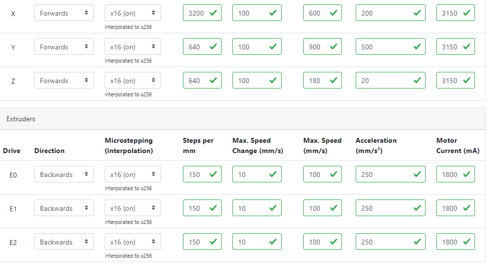
you should aim for about 75% of the rated current.
so around 3150 for the nema23.
and stay with x16 with interpolation for now.
going high puts unnecessary load on the cpu. -
@Veti I have made the changes to 16x and the deviation is still present. Although the amount of deviation is slightly different for requested [actual] readouts: 50 [ 48.5 mm], 100 [102 mm], 150 [155 mm], 200 [210 mm], 250 [265 mm], 300 [317.5]. It seems like the pattern changed but the amount exceeding follows a similar trend starting with low deviation and increasing at 2.5 mm increments as the the requested distance goes up.
 config (1).g
 -
@akhilnex please be aware that 1:5 gears are often 1:5.18 gears (exactly 1: 5+2/11 = 1: 5.181818). The datasheet will tell you.
-
@JoergS5 that's a good point and I think it is true 5:1 planetary reduction gearbox. Here is the link of what I got on Amazon: https://www.amazon.com/dp/B089R8CC1Z/ref=cm_sw_r_cp_apa_fabc_.-m6FbC0RS0XV
Seems like with the new settings the x,y,z axis are running quite accurate. However the NEMA 17 extruder steppers are the one causing trouble.
-
I used these for my belt driven Z axis conversion.
The 5-to-1 is a true 5-to-1.
They have a similar "economy" line product which is not.
Frederick