Toolboard temp sensor resistance
-
Both inputs should have a 10k series resistance so getting less than that is a bit sus?listen to the pros instead

-
You can find the schematics via https://github.com/Duet3D/Duet3-Toolboard-1LC. The resistance readings may take a while to stabilise because of capacitors C35 and C36.
The 103K reading definitely sounds wrong, because TEMP0 is connected via R21 (2K2) to VREFMON which in turn is connected to VSSA via R32 (also 2K2). So I suspect a bad connection.
-
If I do M308 S1 it says last error: short-circuit in sensor. I cant find where that short-circuit would be..
But that would explain why i get 0 degreees instead of 2000 (open-circuit).
Connecting it with a separat cable to main board it gives me correct reading.
Since i might have fried the sensor somehow is it possible to run sensor from MB but still use toolboard for out0?
Not sure if i have missed some settings but if I do that, I get the temperatur but as soon as I activate the tool it shows status fault. -
I just tested a toolboard and Tn->VSSA =~4.36K on both temp inputs
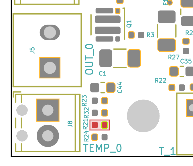
R21 (2K2 resistor between the thermistor input and VREFMON) is close to the header:

Worth checking if that's been disturbed.
I have added the "iBOM" from KiCAD which will allow you to see where all the components are: https://github.com/Duet3D/Duet3-Toolboard-1LC/tree/master/ToolBoard_1LC_v1.0
-
@T3P3Tony Thank you, I will check it
-
-
@KarlMarklund said in Toolboard temp sensor resistance:
If I do M308 S1 it says last error: short-circuit in sensor. I cant find where that short-circuit would be..
You would also get a short-circuit reading if the 2K2 pullup resistor to VREFMON is not connected. So I suggest you check the connections to that resistor. If that resistor is not connected, that would also explain the very high resistance reading you get.
-
@dc42 Hi again, have had much to do so havent had time to check this yet.
Checking it now though and get a reading of about 127K, so it will have to be replaced.While I am at it, should i replace R32 as well, with the same spec resistor? Looks like it is connected to the ADVREF Monitoring.
-
Resistors rarely fail, so please examine that resistor (R21) carefully:
- Is it present?
- Do both ends look soldered down?
- Is there a crack in it?
- What markings does it have on it?
-
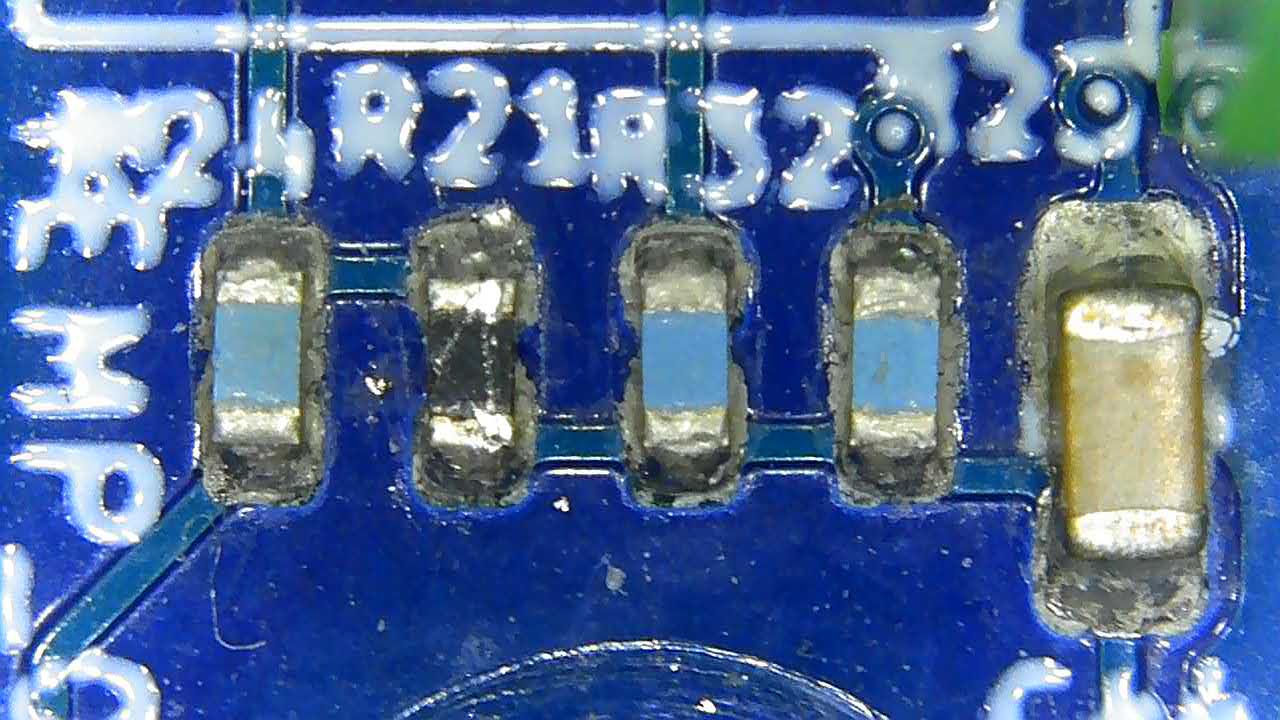
@dc42 it doesnt look healthy, see picture.
Not sure if it should have the same color as the others, or if it is supposed to be black.
-
It's a 0.1% tolerance resistor instead of the usual 1%, that's why it's a different colour. It's also black on the tool board I just looked at on my desk.
Can you try to measure both R21 and R22 with your multimeter? Note, it can be quite difficult to make good multimeter contacts with the ends, I think this is because of the layer of tin oxide on the solder.
-
@dc42 I have scraped a bit to remove any oxidation, but I dont think my multimeter is that accurate (given the result I get for R22).
R21 - 128K
R22 - 1,88Kas ref:
R24 - 9,47K
R32 - 1,87K
R23 - 9,5Would this be a similar resistor to what it should be as a replacement?
https://www.digikey.se/product-detail/en/panasonic-electronic-components/ERA-2AEB222X/P2-2KDCCT-ND/1706191 -
@KarlMarklund, your measurements confirm there is a problem with that resistor, and in your photo it looks like there could be a crack at the bottom end of R21.
As you have changed the connectors, we are unable to offer a replacement under warranty.
The resistor you have linked to looks like a good replacement. Alternatively, you could connect the PT1000 sensor to the other temperature sensor input, unless you are already using that input for something else. -
@dc42 Understandable. Thank you for your assistance, I have ordered that resistor and will try to replace it.
