Mesh comp question
-
I've recently replaced a BL touch with a Precision piezo Orion for my Z probe. The reason I decided to try the Orion was because my height map looked bad on my Mandala Roseworks magbed with pei. The height map looked almost identical with a 3/16 piece of glass on top of the magbed. With the Orion the height map is greatly improved.
I've calibrated the Z probe trigger height to -.028 mm at bed center that prints a nice 1 layer test pattern. I then print 9 20mm X 20mm evenly spaced on the bed 1 layer test patterns. The first pattern starts at the printers front right corner (the corner nearest to me on my left) and goes straight back with 3 patterns, moves right to bed center, prints 3 more moving forward and then over to the right printing 3 more going back. I find that to get the same good first layer that I got with a single center of the bed pattern I need to baby step the bed .1mm closer to the nozzle. The .1mm is needed for a good first layer for 6 of the nine patterns including the center pattern. About 1/2 way through the 7th pattern the rows start to open some so I move the bed .02 mm closer to the nozzle to maintain a good first layer. It stays that way until the end of the print. What can I do to correct this?
Config G
code_text
; Configuration file for Duet 3 (firmware version 3)
; executed by the firmware on start-up
;
; generated by RepRapFirmware Configuration Tool v2.1.8 on Wed Apr 29 2020 12:52:20 GMT-0600 (Mountain Daylight Time)

; General preferences
G90                                                    ; send absolute coordinates...
M83                                                    ; ...but relative extruder moves
M550 P"Duet 3"                                         ; set printer name
M669 K1                                                ; select CoreXY mode

; Configure panelDue
M575 P1 S1 B57600                                      ; set to channel 1, panel due mode with checksum, baud 57600

; Drives
M569 P0.0 S1                                           ; physical drive 0.0 goes forwards
M569 P0.1 S1                                           ; physical drive 0.1 goes forwards
M569 P0.2 S0                                           ; physical drive 0.2 goes backwards
M569 P0.3 S0                                           ; physical drive 0.3 goes backwards

; Bed leveling
M671 X0:157.5:300.0 Y0:300:0                           ; adjusting screws at front left (-3,-1),back middle (160,-320)and right front (320,-1.0)
M584 X0.1 Y0.0 Z0.2 E0.3                               ; set drive mapping Y = drive 0 X = drive 1 Z = drive 2 Extruder drive 3

M350 X16 Y16 Z16 E16 I1                                ; configure microstepping with interpolation
M92 X200.00 Y200.00 Z400.00 E420.00                    ; set steps per mm
M566 X900.00 Y900.00 Z100.00 E120.00                   ; set maximum instantaneous speed changes (mm/min)
M203 X5000.00 Y5000.00 Z600.00 E1200.00                ; set maximum speeds (mm/min)
M201 X500.00 Y500.00 Z20.00 E250.00                    ; set accelerations (mm/s^2)
M906 X800 Y800 Z800 E1000 I30                          ; set motor currents (mA) and motor idle factor in per cent
M84 S30                                                ; Set idle timeout

; Axis Limits
M208 X0 Y0 Z-2.0 S1                                    ; set axis minima
M208 X305 Y305 Z300                                    ; set axis maxima

; Endstops
M574 X1 S1 P"!io1.in"                                  ; configure for low end, active-low endstop on X via pin io1.in
M574 Y1 S1 P"!io2.in"                                  ; configure for low end, active-low endstop on Y via pin io2.in

; Z-Probe
M558 P5 C"!io4.in" H2 F300 R0.5 T6000 A10 S0.003       ; set Z probe to Piezo digital, set input to io 4 in, set dive height,set feed rate, set delay, set speeds
G31 P25 X0 Y0 Z-.028                                   ; set Z probe trigger threshold, Probe X and Y offset and trigger height
M557 X5:300 Y5:300 S26:26                              ; define mesh grid

; Heaters
M308 S0 P"temp0" Y"thermistor" T100000 B4138           ; configure sensor 0 as thermistor on pin temp0
M950 H0 C"out0" T0                                     ; create bed heater output on out0 and map it to sensor 0
M143 H0 S110                                           ; set temperature limit for heater 0 to 110C
M307 H0 A236.8 C516.8 D3.0 V24.1 B0                    ; disable bang-bang mode for the bed heater and set PWM limit
M140 H0                                                ; map heated bed to heater 0
M308 S1 P"temp1" Y"thermistor" T100000 B4138           ; configure sensor 1 as thermistor on pin temp1
M950 H1 C"out1" T1                                     ; create nozzle heater output on out1 and map it to sensor 1
M143 H1 S260                                           ; set temperature limit for heater 1 to 260C
M307 H1 A445.5 C173.0 D5.5 V24.1 B0                    ; disable bang-bang mode for hotend heater and set PWM limit

; Fans
M950 F0 C"out7" Q500                                   ; create fan 0 on pin out7 and set its frequency
M106 P0 S0 H-1                                         ; set fan 0 value. Thermostatic control is turned off
M950 F1 C"out8" Q500                                   ; create fan 1 on pin out8 and set its frequency
M106 P1 S1 H1 T45                                      ; set fan 1 value. Thermostatic control is turned on

; Tools
M563 P0 S"E3D-V6" D0 H1 F0                             ; define tool 0
G10 P0 X0 Y0 Z0                                        ; set tool 0 axis offsets
G10 P0 R0 S0                                           ; set initial tool 0 active and standby temperatures to 0C

; Lights
M950 P1 C"out3"                                        ; Create port on out 3 to power lights, 12v led strips are wired in series


; Custom settings are not defined

; Miscellaneous
T0                                                     ; select first tool
BL touch height map.
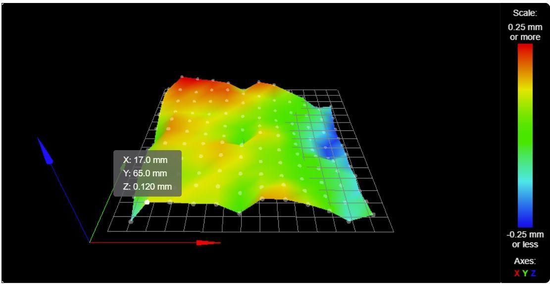
Orion height map
The only change that was made was changing the Z probe.
-
The BLtouch has an offset, so it could be affected by tilt of the print head leading to different trigger heights at different locations on the bed which could explain the overall tilt you see, but that same tilt seems to be present to some degree on the orion map as well.
Are you doing true bed leveling as well? Can you post your homing files and bed.g as well?
-
This Bed G has data relating to the Bl touch. I have not ran a bed g with the Orion yet. The only changes would be to the X Y and Z coordinates.
; bed.g

G28                            ; home all
M561                           ; clear any bed transform

; first run
G30 P0 X-13 Y51 Z-99999        ; probe left front adjusting screw
G30 P1 X135 Y354 Z-99999       ; probe middle rear adjusting screw
G30 P2 X285 Y51 Z-99999 S3     ; probe right front adjusting screw and report adjustments needed

; absolute positioning
G1 X151 Y194 F2000         ; Move probe over to the center of the bed
G30                            ; lower probe, stop when probe triggered and set Z to trigger height, home Z by probing the bed

code_text
Homeall
; homeall.g
; called to home all axes
;
; generated by RepRapFirmware Configuration Tool v2.1.8 on Wed Apr 29 2020 12:52:20 GMT-0600 (Mountain Daylight Time)
G91                     ; relative positioning
G1 H2 Z5 F6000          ; lower bed 5mm to ensure probe is above the Z probe trigger height
G1 H1 X-310 Y-310 F2600  ; move quickly to X or Y endstop and stop there (first pass)
G1 H1 X-310             ; home X axis
G1 H1 Y-310              ; home Y axis
G1 X5 Y5 F6000         ; go back a few mm X and Y
G1 H1 X-310 F360        ; move slowly to X axis endstop once more (second pass)
G1 H1 Y-310 F360         ; then move slowly to Y axis endstop
G90                     ; absolute positioning
G1 X159 Y162 F2600       ; Move probe over to the center of the bed
G30                     ; lower probe, stop when probe triggered and set Z to trigger height, home Z by probing the bed


; Uncomment the following lines to lift Z after probing
;G91                    ; relative positioning
;G1 Z5 F100             ; lift Z relative to current position
;G90                    ; absolute positioning
Ture bed levelling? Hate to sound ignorant but can you explain what that is. I searched the Duet documentation which didn't have anything on true bed leveling.
-
Hi,
Perhaps this will get you started:
https://duet3d.dozuki.com/Wiki/Using_the_manual_bed_levelling_assistant
Frederick
-
@fcwilt, I wondered if that wasn't what true leveling was but wasn't sure. I'll update my bed G and run it which is just an automated version of manual bed leveling ....Right?
-
@luckyflyer said in Mesh comp question:
@fcwilt, I wondered if that wasn't what true leveling was but wasn't sure. I'll update my bed G and run it which is just an automated version of manual bed leveling ....Right?
If you only have bed leveling "thumb screws" then you would use the Manual Bed Leveling Assistant (MBLA).
If you have 2, 3 or 4 independently driven Z steppers you can use Auto Bed Leveling (ABL).
They both use bed.g to probe the bed at different points to determine the needed adjustments to level the bed but MBLA tells you how much to turn each "thumb screw" whereas ABL drives the Z steppers as needed.
Frederick
-
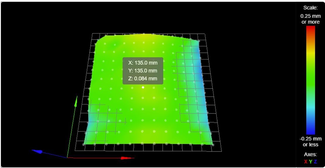
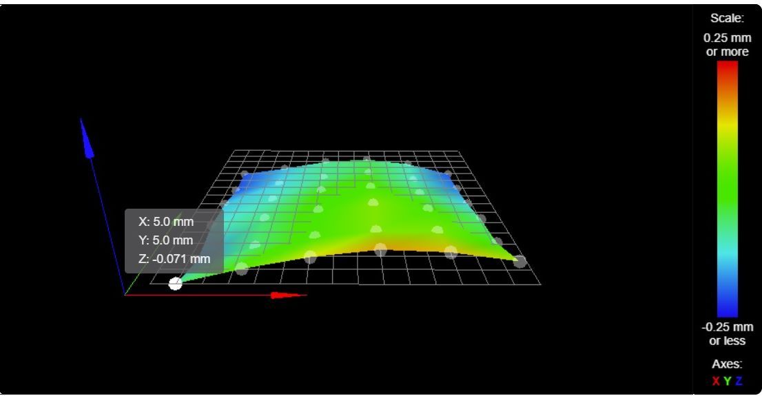
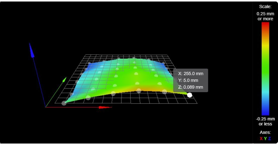
I've ran mbla and finished with the 3 bed points within .01 mm of the master 0,0. I reset the Z height. ran another G29. I had 2 5mm spires on the left side of the h.m for some reason so I reduced the probe points and got this height map.
Question can you tell from a height map if the printer will have trouble in a certain area? It seems to me that sometimes the mesh is not compensating to the level that it should for a good first layer in some areas of the print bed. With no probe offsets there should be no skewing of the map vs actual position.
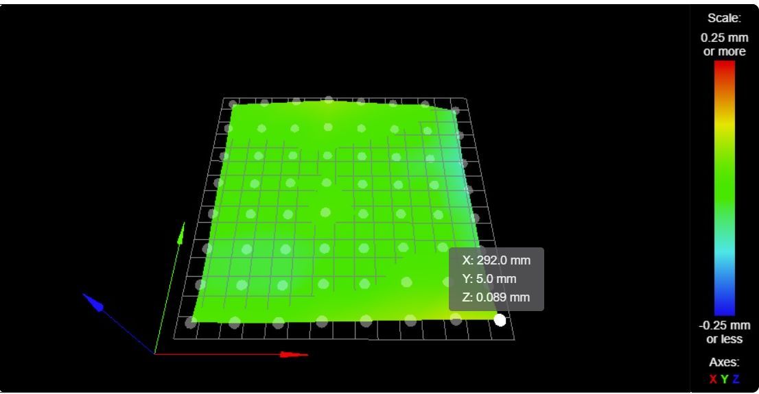
Also I don't understand why the area over the three adjusting screws have such different heights in the heightmap after an mbla. I'm able to probe over all three adjusting screws during a G29. The front left is -.071, front right is +.089 and rear center is somewhere between -.055 and -.079 on the h.m. when the mbla just a few minutes before said the three were within .01 of each other. I could understand if they were above or below the grid but all three should read the same.Wouldn't it be better to home Z at X,Y 0,0 where the master adjust screw is and then adjust bed screws 2 and 3 using the height map to zero them out?
Height map after mbla, G92 Z0 and G29
-
You likely already know this but I will mention it just to be sure:
It's essential to set the Z=0 datum using a single G30 at certain times. And when you do you must always use the same XY point - I use the center of the bed.
- after using G32 to run the Manual Bed Leveling Assistant or Auto Bed Leveling
- when using G29 to create the Height Map needed for using Mesh Compensation - it also enables Mesh Compensation
- when using G29 S1 to load an existing Height Map to enable Mesh Compensation
Moving on...
When using G30 you could use a XY point other than bed center but it isn't going to make any real difference when it comes to actually printing things.
Your height map suggests to me the X gantry is sagging as it moves through the center of it's range. It's possible your bed is shaped like that but I don't think it as likely as X gantry sagging.
BUT you mention using G92 Z0 which is not correct unless you have some specific reason for doing so. If you aren't already doing so you should instead be using G30 to set the Z=0 datum as mentioned above.
Frederick
-
@fcwilt
That is good to know. I used G92 Z0 because that is what is used in the "calibrate the Z probe trigger height" documentation here, https://duet3d.dozuki.com/Wiki/Test_and_calibrate_the_Z_probe
Is there an accepted procedure for checking the gantry while on the printer? I have a straight edge but realise that their true straightness can be questionable. Is there a step by step troubleshooting guide out there somewhere that addresses the issues that I'm having? -
@luckyflyer said in Mesh comp question:
That is good to know. I used G92 Z0 because that is what is used in the "calibrate the Z probe trigger height" documentation here, https://duet3d.dozuki.com/Wiki/Test_and_calibrate_the_Z_probe
G92 Z0 tells the firmware that the current Z position (whatever it may be) is 0 - which of course it may not be.
G30 sets the current Z position value to the Z probe trigger height. If the probe trigger height value is correct then the current Z position value is correct - which is why doing G30 at the specified times is essential.
Is there an accepted procedure for checking the gantry while on the printer? I have a straight edge but realise that their true straightness can be questionable. Is there a step by step troubleshooting guide out there somewhere that addresses the issues that I'm having?
I don't know. Because I knew it could happen when I designed my current printer the two X axis linear guides are mounted on the top and bottom of a 20 x 40 extrusion. The X axis range is 300 mm and there is no discernible sag.
Frederick
-
@fcwilt Thanks for your help and advise. I'm now over on the RepRap forum looking for methods for truing core xy mechanics.
-
With a little tweaking this is what I now have. Hopefully this will make consistent prints anywhere on the bed.
-
That looks very good. All should be well.
Frederick