Help setting probing limits
-
Wondering if anyone has some good recommendations for how best to maximize the probing for my particular situation.
Print head can travel on the
-X axis from 0 to 607mm
-Y axis from 0 to 603mm
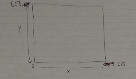
I am using a Bltouch mounted just infront of my hotend and the probe remains above print surface in a smaller range of anything past this range and it may try probing off the bed
-X axis from 5 to 600mm
-Y axis from 47 to 603mm
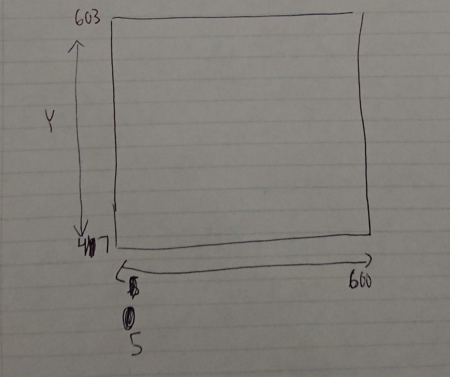
I have tried a few different spacing options but they all seem to not take the Bltouch to the absolute edge which I have defined in the second image
; Axis Limits
M208 X0 Y0 Z0 S1 ; set axis minima
M208 X607 Y603 Z578.5 S0 ; set axis maxima
M208 X0:607 Y0:603 ; max movement allowedM557 X5:600 Y47:603 S20
Any thoughts would be much appreciated!
-
Post your full config.
@singhm29 said in Help setting probing limits:
but they all seem to not take the Bltouch to the absolute edge
You mean the BLTouch isn't as close the front edge as you expect it to be? Use a ruler to measure how far away it is and adjust that distance to your M557 Y minima.
-
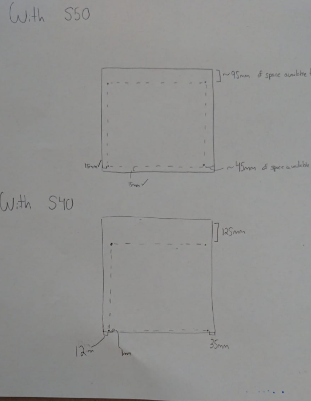
; Configuration file for Duet 3 (firmware version 3)
; executed by the firmware on start-up
;
; generated by RepRapFirmware Configuration Tool v3.2.0 on Wed Jan 06 2021 20:53:06 GMT-0500 (Eastern Standard Time)

; General preferences
G90                                          ; send absolute coordinates...
M83                                          ; ...but relative extruder moves
M550 P"Gigabot"                           ; set printer name

; Network
M552 P0.0.0.0 S1                             ; enable network and acquire dynamic address via DHCP
M586 P0 S1                                   ; enable HTTP
M586 P1 S0                                   ; disable FTP
M586 P2 S0                                   ; disable Telnet

; Drives
M569 P0.0 S1                                 ; physical drive 0.0 goes forwards
M569 P0.1 S0                                 ; physical drive 0.1 goes backwards
M569 P0.2 S1                                 ; physical drive 0.2 goes forwards
M569 P0.3 S1                                 ; physical drive 0.3 goes forwards
M569 P0.4 S1                                 ; physical drive 0.4 goes forwards

M584 X0.0 Y0.1 Z0.2:0.4 E0.3                 ; set drive mapping
M671 X-109:707 Y300:300 S1.0 ; leadscrews at left (connected to Z) and right (connected to E1) of X CHANGE AFTER FIGURE OUT POSITION OF BL ON MOUNT/limits

M350 X16 Y16 Z16 E16 I1                      ; configure microstepping with interpolation
M92 X59.26 Y59.26 Z2015.50 E420.00           ; set steps per mm
M566 X900.00 Y900.00 Z60.00 E7000.00          ; set maximum instantaneous speed changes (mm/min)
M203 X6000.00 Y6000.00 Z180.00 E7000.00      ; set maximum speeds (mm/min)
M201 X500.00 Y500.00 Z20.00 E250.00          ; set accelerations (mm/s^2)
M906 X950 Y1900 Z950:950 E800 I30                ; set motor currents (mA) and motor idle factor in per cent
M84 S30                                      ; Set idle timeout

; Axis Limits
M208 X0 Y0 Z0 S1                             ; set axis minima
M208 X607 Y603 Z578.5 S0                       ; set axis maxima
M208 X0:607 Y0:603 ; max movement allowed

; Endstops
M574 X1 S1 P"!io0.in"                        ; configure active-high endstop for low end on X via pin !io0.in
M574 Y2 S1 P"!io1.in"                        ; configure active-high endstop for high end on Y via pin !io1.in

; Z-Probe
M950 S0 C"io7.out"                           ; create servo pin 0 for BLTouch
M558 P9 C"^io7.in" H5 F120 T6000             ; set Z probe type to bltouch and the dive height + speeds
G31 P25 X-5 Y48 Z2.5                        ; set Z probe trigger value, offset and trigger height
M557 X5:600 Y47:603 S40                     ; define mesh grid

; Heaters
;Bed heater config
M308 S0 P"temp0" Y"thermistor" T100000 B4138 A"Heated bed"; configure sensor 0 as thermistor on pin temp0
M950 H0 C"out0" T0                           ; create bed heater output on out0 and map it to sensor 0
M307 H0 R0.418 C453.0 D4.22 S1.00 V23.9
M307 H0 B1 S1.00                             ; enable bang-bang mode for the bed heater and set PWM limit
M140 H0                                      ; map heated bed to heater 0
M143 H0 S120                                 ; set temperature limit for heater 0 to 120C

;Hotend heater config
;M308 S1 P"temp1" Y"pt1000" A"PT1000"      ; configure sensor 1 as thermocouple via CS pin spi.cs1 PT1000 code
;M950 H1 C"out1" T1                           ; create nozzle heater output on out1 and map it to sensor 1 PT1000 code
M308 S1 P"spi.cs0" Y"rtd-max31865" A"PT100"      ; configure sensor 1 as thermocouple via CS pin spi.cs1 CODE FOR PT100
M950 H1 C"out1" T1                           ; create nozzle heater output on out1 and map it to sensor 1 CODE FOR PT100
M307 H1 B0 S1.00                             ; disable bang-bang mode for heater  and set PWM limit
M143 H1 S450                                 ; set temperature limit for heater 1 to 450C

; Fans
M950 F0 C"out7" Q500                       ; create fan 0 on pin out4 and set its frequency
M106 P0 S0 H-1                               ; set fan 0 value. Thermostatic control is turned off
M950 F1 C"out8" Q500                   ; create fan 1 on pin out5 and set its frequency
M106 P1 S1 H1 T45                            ; set fan 1 value. Thermostatic control is turned on

; Tools
M563 P0 D0 H1 F0                             ; define tool 0
G10 P0 X0 Y0 Z0                              ; set tool 0 axis offsets
G10 P0 R0 S0                                 ; set initial tool 0 active and standby temperatures to 0C

; Custom settings are not defined

; Miscellaneous
T0                                           ; select first tool
Tried S=50 and S=40 this morning and this is how the bounds changed.
@Phaedrux said in Help setting probing limits:
Post your full config.
@singhm29 said in Help setting probing limits:
but they all seem to not take the Bltouch to the absolute edge
You mean the BLTouch isn't as close the front edge as you expect it to be? Use a ruler to measure how far away it is and adjust that distance to your M557 Y minima.
With S40 its perfectly at the front edge but then the back edge suffers and the last row of probing is almost 125mm away. Are you thinking I keep my max travel distances the same but change my min and max? Would that not mess up what homing value is loaded?
-
@singhm29
In M557 also a P parameter is available.
Witch in my opinion is the easier way to define the mesh grid.
So in you case M557 X5:600 Y47:603 P10:10 as a suggestion
The grid than will be calculated for 10x10 points and the machine will drive to the set limits. -
@DIY-O-Sphere said in Help setting probing limits:
M557
That sounds perfect! Thank you for pointing me in the right direction