Duet3D Logo Duet3D
    • Tags
    • Documentation
    • Order
    • Register
    • Login

    Error: bad Command XXX W/RRF 3.2 and leveling issue

    Scheduled Pinned Locked Moved
    General Discussion
    9
    147
    10.8k
    Loading More Posts
    • Oldest to Newest
    • Newest to Oldest
    • Most Votes
    Reply
    • Reply as topic
    Log in to reply
    This topic has been deleted. Only users with topic management privileges can see it.
    • martin7404undefined
      martin7404 @3DPrintingWorld
      last edited by

      @3DPrintingWorld I am remote to the printer 😉 IT is in the shop and I am at home and I am afraid to test it on the camera

      Muldex IDEX Duet2+Duex5
      Custom CoreXY 600x400 Hemera , Duet3+Toolboard+1HCL closed loop
      Sapphire Pro with Duet2, with closed-loop motors
      custom high temp E3D tool changer with Duet2+Duex

      3DPrintingWorldundefined 1 Reply Last reply Reply Quote 0
      • 3DPrintingWorldundefined
        3DPrintingWorld @martin7404
        last edited by

        @martin7404 To be safe you could change it to a negative on the T1 offset then add 2.55mm to your T0 probe offset.

        martin7404undefined 1 Reply Last reply Reply Quote 0
        • martin7404undefined
          martin7404 @3DPrintingWorld
          last edited by

          @3DPrintingWorld I am printing it now with 5 mm offset from the slicer

          Muldex IDEX Duet2+Duex5
          Custom CoreXY 600x400 Hemera , Duet3+Toolboard+1HCL closed loop
          Sapphire Pro with Duet2, with closed-loop motors
          custom high temp E3D tool changer with Duet2+Duex

          3DPrintingWorldundefined 1 Reply Last reply Reply Quote 0
          • 3DPrintingWorldundefined
            3DPrintingWorld @martin7404
            last edited by

            @martin7404 Got it! You are doing it differently but I just wanted to clear up what I said, to add to the probe height you would actually have to subtract.

            1 Reply Last reply Reply Quote 0
            • martin7404undefined
              martin7404
              last edited by

              YES and I canceled it , because slicer offset do not affect the priming

              Muldex IDEX Duet2+Duex5
              Custom CoreXY 600x400 Hemera , Duet3+Toolboard+1HCL closed loop
              Sapphire Pro with Duet2, with closed-loop motors
              custom high temp E3D tool changer with Duet2+Duex

              1 Reply Last reply Reply Quote 0
              • martin7404undefined
                martin7404
                last edited by

                IT is working, showing 0.3 on the DWS screen. IT is in the air , but I can not tell from the camera

                Muldex IDEX Duet2+Duex5
                Custom CoreXY 600x400 Hemera , Duet3+Toolboard+1HCL closed loop
                Sapphire Pro with Duet2, with closed-loop motors
                custom high temp E3D tool changer with Duet2+Duex

                1 Reply Last reply Reply Quote 0
                • martin7404undefined
                  martin7404
                  last edited by

                  I did check one of my backups of the settings a month ago the offset for tool 1 was - and then testing it in manual with panel due I did switch it in some moment

                  Muldex IDEX Duet2+Duex5
                  Custom CoreXY 600x400 Hemera , Duet3+Toolboard+1HCL closed loop
                  Sapphire Pro with Duet2, with closed-loop motors
                  custom high temp E3D tool changer with Duet2+Duex

                  3DPrintingWorldundefined 1 Reply Last reply Reply Quote 0
                  • 3DPrintingWorldundefined
                    3DPrintingWorld @martin7404
                    last edited by

                    @martin7404 That explains it!
                    Last night I erased the firmware a reloaded 3.1.1 and I still have all the same issues..... I must be missing something somewhere.

                    1 Reply Last reply Reply Quote 0
                    • martin7404undefined
                      martin7404
                      last edited by martin7404

                      V3.22 now it shows correct height but prints in the air.
                      Now testing with positive offset.
                      Installed 2nd camera as far I have to go home
                      One more thing on simulation it shows normal heights with positive offset and with printing shows layer+offset

                      Muldex IDEX Duet2+Duex5
                      Custom CoreXY 600x400 Hemera , Duet3+Toolboard+1HCL closed loop
                      Sapphire Pro with Duet2, with closed-loop motors
                      custom high temp E3D tool changer with Duet2+Duex

                      1 Reply Last reply Reply Quote 0
                      • martin7404undefined
                        martin7404
                        last edited by

                        So made a few tests firmware 3.22

                        1. Z offset -2.55 , the DWS shows exact layer height , but the head is about 5 mm up
                        2. Z offset 2.55 and the head is about 5 mm up, and DWC shows layer height + offset
                        3. Ofset iin config is 0 , Shows corect in DWC and the head is 2.55+layer up
                          Tested like that start printing and mid first layer EMERGENCY and measured with steel gauges.
                          I start to thing that this is a bug related to the fact it is IDEX definition in TOOLS section of config.g

                        Muldex IDEX Duet2+Duex5
                        Custom CoreXY 600x400 Hemera , Duet3+Toolboard+1HCL closed loop
                        Sapphire Pro with Duet2, with closed-loop motors
                        custom high temp E3D tool changer with Duet2+Duex

                        1 Reply Last reply Reply Quote 0
                        • martin7404undefined
                          martin7404
                          last edited by martin7404

                          Rollback to 3.11 and PANEL DUE to 1.24
                          Same story
                          With an offset of -2.55 on tool1 it is showing correct layer height and is about 5 mm up
                          Tried to disable the tool2 (copy mode in case this is messing), no efect I am starting to think, that because with + offset, shorter hotend than no tool, the duet has some failsafe no to hit the gantry. I will try to add 2.55 to probe and -2.55 to T0 ( loading TO with the config, of course )

                          Muldex IDEX Duet2+Duex5
                          Custom CoreXY 600x400 Hemera , Duet3+Toolboard+1HCL closed loop
                          Sapphire Pro with Duet2, with closed-loop motors
                          custom high temp E3D tool changer with Duet2+Duex

                          1 Reply Last reply Reply Quote 0
                          • martin7404undefined
                            martin7404
                            last edited by

                            It is working the - offset is in tool0 and tool1 have 0 offset, th probe ofset is now bigger

                            Muldex IDEX Duet2+Duex5
                            Custom CoreXY 600x400 Hemera , Duet3+Toolboard+1HCL closed loop
                            Sapphire Pro with Duet2, with closed-loop motors
                            custom high temp E3D tool changer with Duet2+Duex

                            Phaedruxundefined 1 Reply Last reply Reply Quote 0
                            • Phaedruxundefined
                              Phaedrux Moderator @martin7404
                              last edited by

                              @martin7404 said in Error: bad Command XXX W/RRF 3.2 and leveling issue:

                              It is working the - offset is in tool0 and tool1 have 0 offset, th probe ofset is now bigger

                              I've been trying to follow along. Are you saying it's working as expected now?

                              Z-Bot CoreXY Build | Thingiverse Profile

                              1 Reply Last reply Reply Quote 0
                              • martin7404undefined
                                martin7404
                                last edited by martin7404

                                yes
                                first print finished with tool1 (left) 🙂
                                here is my new config
                                It is with PRF3.11 and I think It will work with PRF3.22 too

                                G90                                             ; send absolute coordinates...
                                M83                                             ; ...but relative extruder moves
                                M550 P"Muldex"                                  ; set printer name
                                
                                
                                ; Network
                                M552 S1                                        ; enable network
                                M586 P0 S1                                      ; enable HTTP
                                M586 P1 S0                                      ; disable FTP
                                M586 P2 S0                                      ; disable Telnet
                                
                                ; Drives
                                M569 P0 S0                                      ; X physical drive 0 goes backwards
                                M569 P1 S0                                      ; Y right physical drive 1 goes backwards
                                M569 P2 S1                                      ; Y left physical drive 2 goes forwards
                                M569 P3 S1                                      ; U physical drive 3 goes forwards
                                M569 P4 S1                                     ; E1 physical drive 4 goes backwards
                                M569 P5 S1                                      ; Z left physical drive 5 goes backwards
                                M569 P6 S1                                     ; Z center physical drive 6 goes backwards
                                M569 P7 S0                                      ; Z right physical drive 7 goes forwards
                                M569 P8 S1                                      ; E2 physical drive 8 goes forwards
                                
                                M584 X0 Y1:2 U3 Z5:6:7 E4:8                     ; set drive mapping
                                
                                M350 X16 U16 Y16 Z16 E16:16 I1                                                           ; configure microstepping with interpolation
                                M92 X199.7 U200 Y199.8:199.8 Z799.2:799.2:799.2 E813.07:830.00                        ; set steps per mm (1760nimble)
                                M566 X1000.00 U1000.00 Y1000.00:1000.00 Z80.00:80.00:80.00 E100.00:100.00                ; set maximum instantaneous speed changes (mm/min)(Nimble 40)
                                M203 X12000.00 U12000.00 Y12000.00:12000.00 Z1000.00:1000.00:1000.00 E4200.00:4200.00    ; set maximum speeds (mm/min)
                                M201 X1310.00 U1310.00 Y1310.00:1310.00 Z35.00:35.00:35.00 E800.00:800.00                    ; set accelerations (mm/s^2)(500)(Nimble 120)
                                M906 X900 U900 Y900:900 Z900:900:900 E1000:1000 I30                                        ; set motor currents (mA) and motor idle factor in per cent(Nimble 500)
                                M84 S120                                                                                  ; Set idle timeout
                                
                                ; Axis Limits
                                M208 X-18 Y0 U40 Z0 S1                          ; set axis min - adjust X to align nozzle
                                M208 X350 U422.7 Y333 Z300 S0                   ; set axis max 
                                
                                M669 K0 Y1:-1:0:1				                ; select Markforged Kinematics Y to react with X and U
                                
                                ; Endstops
                                M574 X1 S1 P"xstop"                             ;X axis active high endstop switch
                                M574 Y2 S1 P"ystop+e1stop"                      ;Y Double max active high endstop switch
                                ;M574 Y1 S4 ; configure sensorless endstop for low end on Y
                                M574 U2 S1 P"e0stop"                            ;U axis active high endstop switch
                                ;M574 Z2 S4
                                
                                ;Stall Detection(no used)
                                ;M574 Y1 S4                                     ; Y axis stall detection
                                ;M915 P1:9 S3 F1 R0                             ; Y axis stall detection
                                
                                ; Z-Probe
                                M671 X-20.6:200:420.6 Y14.3:333.3:14.3 S10       ; Locations left, center, right          
                                M950 S0 C"duex.e6heat"                          ; create servo pin 0 for BLTouch
                                M558 P9 C"zprobe.in+zprobe.mod" H10 F600 A1 T12000   ; set Z probe type to bltouch and the dive height + speeds 
                                G31 P25 X-29 Y0 Z3.97                           ; set Z probe trigger value, offset and trigger height(lower number farther away)1.8build 1.7glass 
                                M557 X10:320 Y20:290 S60                       ; probe from X=10 to 390, Y=10 to 290mm with a mesh spacing of 20mm
                                
                                ; Heaters
                                M308 S0 P"bedtemp" Y"thermistor" T100000 B4534 C9.565227e-8      ; configure sensor 0 as thermistor on pin bedtemp
                                M950 H0 C"bedheat" T0                                            ; create bed heater output on bedheat and map it to sensor 0
                                M143 H0 S120                                                     ; set temperature limit for heater 0 to 120C
                                M307 H0 B0 S1.00                                                 ; disable bang-bang mode for the bed heater and set PWM limit
                                M140 H0                                                          ; map heated bed to heater 0
                                M308 S1 P"e0temp" Y"thermistor" T100000 B4725 C0 R4700  ; configure sensor 1 as thermistor on pin e0temp
                                M950 H1 C"e0heat" T1                                             ; create nozzle heater output on e0heat and map it to sensor 1
                                M143 H1 S280                                                     ; set temperature limit for heater 1 to 280C
                                M307 H1 B0 S1.00                                                 ; disable bang-bang mode for heater  and set PWM limit
                                M308 S2 P"e1temp" Y"thermistor" T100000 B4725 C0 R4700 ; configure sensor 2 as thermistor on pin e1temp
                                M950 H2 C"e1heat" T2                                             ; create nozzle heater output on e1heat and map it to sensor 2
                                M143 H2 S280                                                     ; set temperature limit for heater 2 to 280C
                                M307 H2 B0 S1.00                                                 ; disable bang-bang mode for heater  and set PWM limit
                                
                                ; Fans
                                M950 F0 C"fan0" Q500                             ; create fan 0 on pin fan0 and set its frequency
                                M106 P0 S0 H-1                               ; set fan 0 value. Thermostatic control is turned off
                                M950 F1 C"fan1" Q500                             ; create fan 1 on pin fan1 and set its frequency
                                M106 P1 S1 H1 T45                                ; set fan 1 value. Thermostatic control is turned on
                                M950 F2 C"fan2" Q500                             ; create fan 2 on pin fan2 and set its frequency
                                M106 P2 S0 H-1                                   ; set fan 2 value. Thermostatic control is turned off
                                M950 F3 C"duex.fan8" Q500                        ; create fan 3 on pin duex.fan8 and set its frequency
                                M106 P3 S1 H2 T45                                ; set fan 3 value. Thermostatic control is turned on
                                
                                ; LEDs
                                M950 F4 C"duex.fan6" ;Q500                       ; create LED 4 on pin duex.fan6 and set its frequency
                                M106 P4 S128 H-1                                 ; set LED 4 value. Thermostatic control is turned OFF
                                M950 F5 C"duex.fan7" ;Q500                       ; create LED 5 on pin duex.fan7 and set its frequency
                                M106 P5 S128 H-1                                 ; set LED 5 value. Thermostatic control is turned OFF
                                
                                ; Tools
                                M563 P0 D0 H1 F0 S"Left"                         ; define tool 0 Left 
                                G10 P0 X0 Y0 Z-2.55                             ; set tool 0 axis offsets y was .45
                                G10 P0 R0 S0                                     ; set initial tool 0 active and standby temperatures to 0C
                                
                                M563 P1 D1 H2 X3 F2 S"Right"                     ; define tool 1 Right
                                G10 P1 X0 Y0 Z0                ; set tool 1 axis offsets - adjust Y to alignn nozzle
                                G10 P1 R0 S0                                     ; set initial tool 1 active and standby temperatures to 0C
                                
                                ;M563 P2 D0:1 H1:2 X0:3 F0:2 S"Copy"              ; define tool 2 Copy
                                ;G10 P2 X90 Y0 U-90 S0 R0                         ; set tool 2 axis offsets (WAS 105)
                                ;M567 P2 E1:1         
                                ;M568 P2 S1 ; turn on mixing for tool 2           ; set mix ratio 100% on both extruders
                                ;G10 L1 P1 X0.0 Y0.0 Z-2.55
                                
                                M501                                             ; Record
                                M593 F66.6
                                T0 PO
                                M575 P1 S1 B57600                                ;Panel due 
                                ;G92 Z150
                                ;G91
                                ;G1 Z0.1 f100
                                ;G90
                                

                                Untitled.png

                                Muldex IDEX Duet2+Duex5
                                Custom CoreXY 600x400 Hemera , Duet3+Toolboard+1HCL closed loop
                                Sapphire Pro with Duet2, with closed-loop motors
                                custom high temp E3D tool changer with Duet2+Duex

                                3DPrintingWorldundefined 1 Reply Last reply Reply Quote 1
                                • 3DPrintingWorldundefined
                                  3DPrintingWorld @martin7404
                                  last edited by

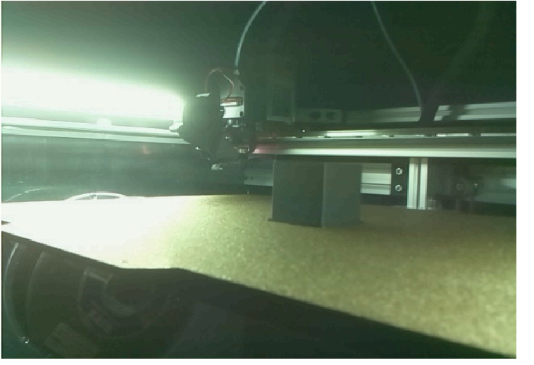
                                  @martin7404 That is great news Martin!

                                  1 Reply Last reply Reply Quote 1
                                  • martin7404undefined
                                    martin7404
                                    last edited by

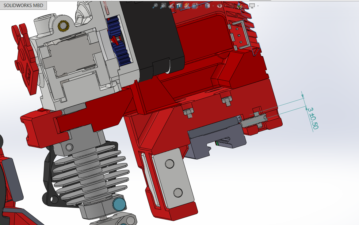
                                    @3DPrintingWorld There is slight problem with such a diference 2.55 when the left head is near the Y0, so temp solution is to put a shim of 3 mm between the MGN9 block and the X cariage

                                    Muldex IDEX Duet2+Duex5
                                    Custom CoreXY 600x400 Hemera , Duet3+Toolboard+1HCL closed loop
                                    Sapphire Pro with Duet2, with closed-loop motors
                                    custom high temp E3D tool changer with Duet2+Duex

                                    1 Reply Last reply Reply Quote 0
                                    • martin7404undefined
                                      martin7404
                                      last edited by martin7404

                                      So Put X carriage on 3mm plate and now both hot ends are alignedUntitled.png

                                      Muldex IDEX Duet2+Duex5
                                      Custom CoreXY 600x400 Hemera , Duet3+Toolboard+1HCL closed loop
                                      Sapphire Pro with Duet2, with closed-loop motors
                                      custom high temp E3D tool changer with Duet2+Duex

                                      3DPrintingWorldundefined 2 Replies Last reply Reply Quote 0
                                      • 3DPrintingWorldundefined
                                        3DPrintingWorld @martin7404
                                        last edited by

                                        @martin7404 I see your point. Good idea though, much easier then trying to move the other hotend down.
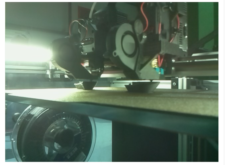
                                        1 Reply Last reply Reply Quote 0
                                        • martin7404undefined
                                          martin7404
                                          last edited by

                                          copy mode working
                                          Untitled1.png

                                          Muldex IDEX Duet2+Duex5
                                          Custom CoreXY 600x400 Hemera , Duet3+Toolboard+1HCL closed loop
                                          Sapphire Pro with Duet2, with closed-loop motors
                                          custom high temp E3D tool changer with Duet2+Duex

                                          1 Reply Last reply Reply Quote 1
                                          • 3DPrintingWorldundefined
                                            3DPrintingWorld @martin7404
                                            last edited by

                                            @martin7404 I'll have to look at the step file on the github. I dont think I looked at the file after I converted it. I did not realize that I had the Orbiter, it was supposed to have two BMG's.

                                            1 Reply Last reply Reply Quote 0
                                            • First post
                                              Last post
                                            Unless otherwise noted, all forum content is licensed under CC-BY-SA