Designing a PWM to Analog mini board for fans
-
@bks31 said in Designing a PWM to Analog mini board for fans:
@Egon-Net im intrested also in your custoim changer as well
Do you mean my tool changer printer?
-
@bks31 said in Designing a PWM to Analog mini board for fans:
@Egon-Net im intrested also in your custoim changer as well
yes wasnt sure if you were making like a attachment for the carraige
-
@bks31 said in Designing a PWM to Analog mini board for fans:
@bks31 said in Designing a PWM to Analog mini board for fans:
@Egon-Net im intrested also in your custoim changer as wellyes wasnt sure if you were making like a attachment for the carraige
It's a custom motion system, 300mmx300mmx300mm CoreXY, with e3d toolchanger plates...
-
@Egon-Net said in Designing a PWM to Analog mini board for fans:
Any suggestion?
All sounds reasonable to me. As for the LEDS, since they are for indication only, you can easily have a 1:4 voltage range (e.g. 2 to 8ma) without going out of spec.
They are nice for diagnostics, but not absolutely required IMO.
-
Well, I have one fan that is pwm regulated so, at least for now I’m in to one PCB also
")
My printer is a Longer LK4, but if that’s not a concern then perfect.Do you think is easy to implement something like a 8v-24v range?
Regards
-
@marcelorider said in Designing a PWM to Analog mini board for fans:
Well, I have one fan that is pwm regulated so, at least for now I’m in to one PCB also
My printer is a Longer LK4, but if that’s not a concern then perfect.Do you think is easy to implement something like a 8v-24v range?
Regards
You can limit the PWM in M106 gcode so if it's less than a value, a minimum value is set (8V->33% equivalent for your case). The bad side is that from 0% to 33%, it would output the same 8V.
I'm afraid there's not an easy way to limit the lower side as you'd need.
-
Just a reminder that if you are not using a fan output on a DueX2 or DueX5 board, you can increase the PWM frequency to 65535 and then use a simple LC filter, i.e. capacitor in parallel with the fan, and an inductor between the Duet FAN- output and the negative fan wire + capacitor. Suitable component values would be 1mH and 1uF. For the inductor, part # 13R105C is widely available and rated up to 330mA, which should be sufficient for most fans used in 3D printers.
If using a heater output on a Duet 2 to drive a fan with LC filter, you also need to add a flyback diode across the output terminals.
DueX boards have a fixed PWM frequency, so this approach would need a much larger inductor, making is impractical unless you have some old transformers lying around.
Duet WiFi hardware designer and firmware engineer
Please do not ask me for Duet support via PM or email, use the forum
http://www.escher3d.com, https://miscsolutions.wordpress.com -
@dc42 said in Designing a PWM to Analog mini board for fans:
Just a reminder that if you are not using a fan output on a DueX2 or DueX5 board, you can increase the PWM frequency to 65535 and then use a simple LC filter, i.e. capacitor in parallel with the fan, and an inductor between the Duet FAN- output and the negative fan wire + capacitor. Suitable component values would be 1mH and 1uF. For the inductor, part # 13R105C is widely available and rated up to 330mA, which should be sufficient for most fans used in 3D printers.
If using a heater output on a Duet 2 to drive a fan with LC filter, you also need to add a flyback diode across the output terminals.
DueX boards have a fixed PWM frequency, so this approach would need a much larger inductor, making is impractical unless you have some old transformers lying around.
That's the very reason I'm doing all of this: I'm driving 6 fans from a Duex 5 board, and I already calculated that the inductor for a LC filter would be huge, and I'd need 6 of them. That's why I went with this route. But thanks for the advice!
-
@Egon-Net
Thanks for the reply.
Honestly I don’t use it below 50% so I don’t think that would be a problem.
Although as of now the fan doesn’t even spin correctly with any pwm state and just rotates above 50% but so slow, not controllable by any means. -
@Egon-Net said in Designing a PWM to Analog mini board for fans:
That's the very reason I'm doing all of this: I'm driving 6 fans from a Duex 5 board, and I already calculated that the inductor for a LC filter would be huge, and I'd need 6 of them. That's why I went with this route. But thanks for the advice!
Have you determined what it is about your fans that cause them to not work with PWM?
I have dozens of different kinds of brushless fans from many different vendors and they all work fine with PWM.
Thanks.
Frederick
-
@fcwilt said in Designing a PWM to Analog mini board for fans:
@Egon-Net said in Designing a PWM to Analog mini board for fans:
That's the very reason I'm doing all of this: I'm driving 6 fans from a Duex 5 board, and I already calculated that the inductor for a LC filter would be huge, and I'd need 6 of them. That's why I went with this route. But thanks for the advice!
Have you determined what it is about your fans that cause them to not work with PWM?
I have dozens of different kinds of brushless fans from many different vendors and they all work fine with PWM.
Thanks.
Frederick
Yes, I've done quite a lot of test. Some of my fans don't work at all as soon as you drop from 99% PWM. Most of them work, but PWM is not linear at all: 99% is already less than 25% airflow, and 50% PWM is no much less than that, and some of them kinda work with PWM, but whinning an awful lot, since they are connected to a Duex5 and I cannot change PWM frequency at all.
I suppose that 4010 fans, and even more, 4010 brushless radial fans are very tricky to get working with PWM.By contrast, using my bench power supply, all of them work more or less linearly, at the very least from 12V to 24V.
In my other old printer (an old cartesian Marlin based custom one) I'm using 4020 and 5015 radial fans and managed to get some fans that work ok with PWM.
-
@Egon-Net said in Designing a PWM to Analog mini board for fans:
Yes, I've done quite a lot of test. Some of my fans don't work at all as soon as you drop from 99% PWM. Most of them work, but PWM is not linear at all: 99% is already less than 25% airflow
That doesn't make sense.
According to my oscilloscope 100% is pure DC and 99% is 99% "pure DC".
It seems strange that those 1% intervals where the power to the fan drops to 0 would reduce the airflow to 25%.
Weird.
Frederick
Printers: a small Utilmaker style, a small CoreXY and a E3D MS/TC setup. Various hotends. Using Duet 3 hardware running 3.4.6
-
@fcwilt said in Designing a PWM to Analog mini board for fans:
It seems strange that those 1% intervals where the power to the fan drops to 0 would reduce the airflow to 25%.
I think that those fans are driven by electronics that is embedded in them. Once the PWM cuts the power to the electronics, it's difficult to predict how that electronic will behave, unless it's guaranteed by its datasheet.
Powering electronics that expects DC voltage with intermittent power is a hack. (No offense, I do it as well).
-
@fcwilt said in Designing a PWM to Analog mini board for fans:
@Egon-Net said in Designing a PWM to Analog mini board for fans:
Yes, I've done quite a lot of test. Some of my fans don't work at all as soon as you drop from 99% PWM. Most of them work, but PWM is not linear at all: 99% is already less than 25% airflow
That doesn't make sense.
According to my oscilloscope 100% is pure DC and 99% is 99% "pure DC".
It seems strange that those 1% intervals where the power to the fan drops to 0 would reduce the airflow to 25%.
Weird.
Frederick
As @zapta said, brushless motors are driven by embedded electronics, they are not just inductors and magnets. And some electronics are very susceptible to supply anomalies. If you do something like this to an opamp, it will easily begin to oscilate. The 99% "pure DC" has 250 narrow gnd peaks per second, which generates infinite harmonics that can and indeed disturb most electronics. If you have an original e3d V6, try to PWM its 24V 3010 fan. It will stop as soon as PWM is activated, no matter the %. And if you have a 24V 4010 radial fan from TriangleLabs (if they have not changed the source) try to PWM it, and witness the speed fall once you go to a non-100% PWM.
-
@Egon-Net said in Designing a PWM to Analog mini board for fans:
If you have an original e3d V6, try to PWM its 24V 3010 fan. It will stop as soon as PWM is activated
I dug one out of my inventory and sure enough that fan doesn't work worth a hoot on PWM.
Now I have to go through my entire inventory of fans and see if all of each model work on PWM or I just got stupid lucky and picked out ones that did.
You could have left me in blissful ignorance but no, you had to go and educate me.
While I test my inventory I will think of you fondly
")
Frederick
-
@dc42 said in Designing a PWM to Analog mini board for fans:
For the inductor, part # 13R105C is widely available and rated up to 330mA
I added it to my digikey to-purchase list. Will try next time I order, out of curiosity.
-
First draft for the PCB, still lacks proper connectors and labeling. It measures 20x38mm.
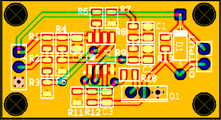
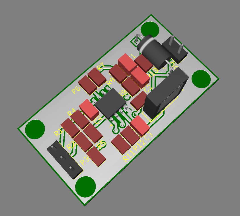
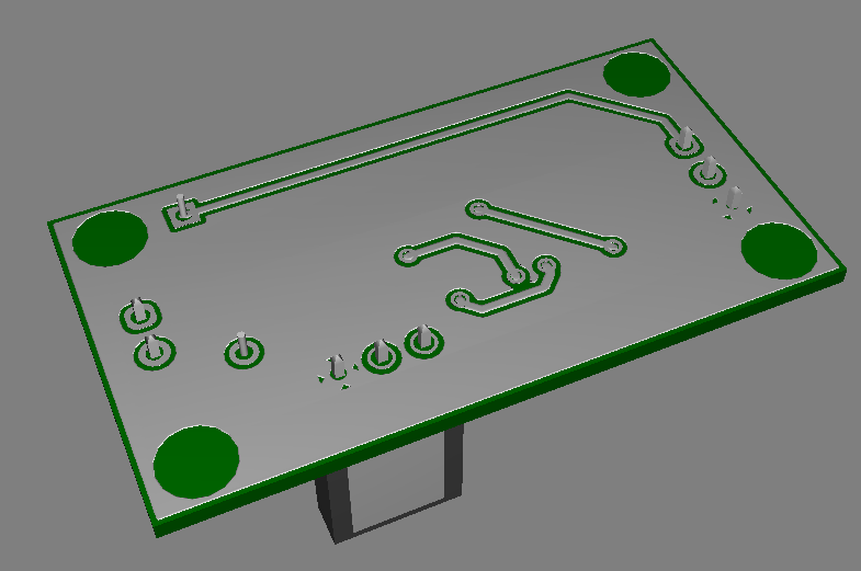
I could add a smd resistor + led in the back side just for those who want to populate it in parallel with the output. And maybe I'd move the transistor to the border to let vertical space for the heatsink outside the pcb...
Thoughts? Suggestions?
-
Looks good.
You can raise the cuteness level by rounding the corners.
I think that by soldering right angle connector and bending the transistor, they can also be stacked up using spacers, which is nice.
-
@zapta said in Designing a PWM to Analog mini board for fans:
Looks good.
You can raise the cuteness level by rounding the corners.
I think that by soldering right angle connector and bending the transistor, they can also be stacked up using spacers, which is nice.
Do you mean rounding the trace corners or the pcb itself?
-
@Egon-Net, the PCB itself. Some makers do it, I think for the more friendly look.