DUET 3 SSD SOLID STATE RELAYS How to connect?
-
Hello the duet3 comes next week, and I'm not sure at the wiring, would be friendly if someone could help me before I scrap.
I am working on using a Duet 3-Setup with 230-V silicone Heating Pad and SSD Solid State Relays, but I'm not sure like me the SSD with the board wiring.
I do not want to go over the MOSFET OF OUT0, but connect via an output out_4 to out_9.
But how do I tab the SSD Plus (+) and minus (-), it has four different connections at out_4 to out_6- GND
- V_OOUTLC1
- out4.tach
- Out4
At out_7 to out_9 two connections
- V_OUTLC2
- Out7
And I can configure the heating bed and the temperature sensor in the Duet Web Control, or via G-cods.
Say already thank you for the help. Greeting

-
@TORX_1 why don't you want to use OUT 0?
Follow my adventures in 3D Printing, laser cutting and electronics. https://linktr.ee/Rushmere3D
-
I do not want to switch twice, the Mosfet of Out0, and the SSD.
-
@TORX_1 I have my Keenovo AC bed connected via OUT 0 and an SSR it works perfectly.
-
@TORX_1 said in DUET 3 SSD SOLID STATE RELAYS How to connect?:
I do not want to switch twice, the Mosfet of Out0, and the SSD.
Why not? It is simple and works fine. There is no reason not to do it that way.
Frederick
-
@TORX_1 said in DUET 3 SSD SOLID STATE RELAYS How to connect?:
I do not want to switch twice, the Mosfet of Out0, and the SSD.
Either way it's still switching a signal voltage for the SSR.
If you wish to use the Out0 for something else, that's fine though, you can use any of the low current outputs to switch the SSR signal.
The natural choice would be to use one of the other heater outputs (OUT1, 2, 3), but if you insist on wanting to use out4 - 9 connector you could do that as well.
4-pin KK connectors with offset spigot OUT_4 thru OUT_6: these are intended for PWM-controllable fans. The connector fits a standard PC-type 4-pin PWM fan. Alternatively, a 2-pin fan may be connected between the V_OULCn pin (+ve) and the OUT_n_NEG pin (-ve). The positive supply to these connectors is the centre pin of the 3-pin jumper block labelled OUT4-OUT6_Select. A jumper in the top position will power them from the fused VIN supply. Alternatively you can connect a 3-terminal buck regulator to the 3-pin jumper block to supply the required voltage to the centre pin.
2-pin KK connectors labelled OUT7 thru OUT9: these are intended for fans. Maximum recommended current 2.5A each. Flyback diodes are built-in to these outputs.
You would want to connect to V_OOUTLC1 (for positive) and Out4 (pwm signal is on negative side)
The pin usage is defined in the config with M950 command.
-
@Phaedrux Thank you for the quick answer now I'm calmed down.
Is that in the picture as so feasible? And that's better to OUT1 to OUT3 than OUT7-OUT9 with Juper on V_IN (24V).
There are certainly a few questions more in the next few weeks, but I'm in good hands here.
Thank you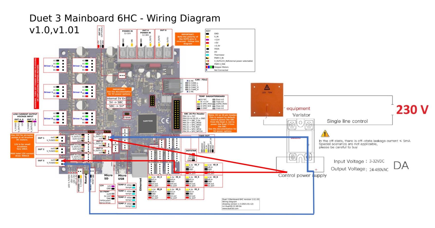
-
If it were me, I would use Out0 for the bed and leave out1 2 3 as extruders. But if you wanted out0 free and had a free extruder port open I would use that and leave out4-9 as fans, etc.
The point is though, it's flexible and you can use the ports as needed. There is no fixed function for the pins other than the current carrying capacity of the ports and availability of PWM control.
-
@Phaedrux That's the good thing that is so flexible with the DUET3, I use your advice then out0 for the bed and leave 1 2 3 as an extruder away.
This does not burden the board no more than with OUT1-OUT3, two thick cables are more from the power supply to OUT0-POWER-IN and OUT0 for SSR or bridges of power-in.
Thanks again for the explanation and proposal.