Duet3D Logo Duet3D
    • Tags
    • Documentation
    • Order
    • Register
    • Login

    How is the “Height Map” Used?

    Scheduled Pinned Locked Moved
    General Discussion
    3
    27
    4.4k
    Loading More Posts
    • Oldest to Newest
    • Newest to Oldest
    • Most Votes
    Reply
    • Reply as topic
    Log in to reply
    This topic has been deleted. Only users with topic management privileges can see it.
    • tmeryhewundefined
      tmeryhew
      last edited by

      I’ve looked around online and see a lot of helpful information on how to set up a z probe and get all of that dialed in.

      But can someone explain to me just how and when exactly the height map is used? Is it automatic? Do I need to reconfigure printer settings in my slicer?

      Thanks in advance!

      1 Reply Last reply Reply Quote 0
      • Phaedruxundefined
        Phaedrux Moderator
        last edited by

        This may help: https://duet3d.dozuki.com/Wiki/Using_mesh_bed_compensation

        Z-Bot CoreXY Build | Thingiverse Profile

        tmeryhewundefined 1 Reply Last reply Reply Quote 0
        • tmeryhewundefined
          tmeryhew @Phaedrux
          last edited by tmeryhew

          @Phaedrux I read through that page. I'm still not understanding what is actually being done with the height map once it is created and stored.

          Any idea what the process is for how the data points are incorporated into a file that is being printed? I just want to confirm that its actually being used to improve my first layers.

          Here is my start Code:

          G28 ;Home
          G29 ; Auto Bed Leveling

          G92 E0 ;Reset Extruder
          G1 Z2.0 F3000 ;Move Z Axis up
          G1 X10.1 Y20 Z0.28 F5000.0 ;Move to start position
          G1 X10.1 Y200.0 Z0.28 F1500.0 E15 ;Draw the first line
          G1 X10.4 Y200.0 Z0.28 F5000.0 ;Move to side a little
          G1 X10.4 Y20 Z0.28 F1500.0 E30 ;Draw the second line
          G92 E0 ;Reset Extruder
          G1 Z2.0 F3000 ;Move Z Axis up

          fcwiltundefined Phaedruxundefined 2 Replies Last reply Reply Quote 0
          • tmeryhewundefined
            tmeryhew
            last edited by

            23542cf4-f7a6-470b-a796-9cbc6af17f75-image.png

            1 Reply Last reply Reply Quote 0
            • fcwiltundefined
              fcwilt @tmeryhew
              last edited by

              @tmeryhew said in How is the “Height Map” Used?:

              @Phaedrux I read through that page. I'm still not understanding what is actually being done with the height map once it is created and stored.

              Any idea what the process is for how the data points are incorporated into a file that is being printed? I just want to confirm that its actually being used to improve my first layers.

              Here is my start Code:

              G28 ;Home
              G29 ; Auto Bed Leveling

              G92 E0 ;Reset Extruder
              G1 Z2.0 F3000 ;Move Z Axis up
              G1 X10.1 Y20 Z0.28 F5000.0 ;Move to start position
              G1 X10.1 Y200.0 Z0.28 F1500.0 E15 ;Draw the first line
              G1 X10.4 Y200.0 Z0.28 F5000.0 ;Move to side a little
              G1 X10.4 Y20 Z0.28 F1500.0 E30 ;Draw the second line
              G92 E0 ;Reset Extruder
              G1 Z2.0 F3000 ;Move Z Axis up

              The action of the height map and how it is used for mesh compensation is fairly simple.

              For each grid point on the height map the firmware can read from the height map file how much above or below the reference point (see G30) that grid point is.

              For any XY position that information can be used to determine how much above or below the reference point the point at that XY position is.

              So using that ability when printing the firmware, based on the current XY position, "tweaks" the Z position based up or down as needed to better follow the irregularities of the bed.

              The height map needs to be loaded and mesh compensation enabled for that all to happen.

              If you want to see it in action in a very clear way I could send you a 4 point height map using extreme height variation from left to right such that when you jogged the X axis from its min value to its max value you can clearly see the Z position being "tweaked".

              Frederick

              Frederick

              Printers: a small Utilmaker style, a small CoreXY and a E3D MS/TC setup. Various hotends. Using Duet 3 hardware running 3.4.6

              tmeryhewundefined 1 Reply Last reply Reply Quote 0
              • tmeryhewundefined
                tmeryhew @fcwilt
                last edited by

                @fcwilt so looking at my start code I posted above, am I doing this right?

                Are there any additional steps I need to take to ensure this is being incorporated into my first layers?

                Thanks for responding and giving more info. I really appreciate this. I feel like I am either there, or damn close.

                fcwiltundefined 1 Reply Last reply Reply Quote 0
                • fcwiltundefined
                  fcwilt @tmeryhew
                  last edited by fcwilt

                  @tmeryhew said in How is the “Height Map” Used?:

                  @fcwilt so looking at my start code I posted above, am I doing this right?

                  Are there any additional steps I need to take to ensure this is being incorporated into my first layers?

                  Thanks for responding and giving more info. I really appreciate this. I feel like I am either there, or damn close.

                  Well I'm not sure what you are doing with the extruder there - priming it I guess?

                  In any case to use the height map you need to do two things at the start of the print

                  1 - set the Z=0 datum
                  2 - load the desired height map

                  To do this you need the following commands in your start code before any commands that try to print;

                  G90
                  G1 Xaaa Ybbb Fccc 
                  G30
                  G29 S1 or G29 S1 P"name_of_height_map_file.csv"
                  

                  The G90 insures you are in absolute positioning mode for the following G1 command.

                  The G1 command is needed to move the Z probe (not the nozzle) to the center of your bed. The values aaa and bbb you have to compute so that the Z probe ends up at the center of your bed. The value ccc sets the move speed to whatever speed you wish.

                  The G30 command probes thebolded text bed and sets the Z=0 datum that is needed to load the height map.

                  The G29 S1 will load the height map file using the default file name heightmap.csv. To load any other heightmap you use G29 S1 with the P parameter specifying the name of the file.

                  Remember when creating and when loading a height map the Z=0 datum must be set first and it must always be at the same XY position and the best XY position is the center of the bed.

                  If that is not clear just let me know.

                  Frederick

                  Printers: a small Utilmaker style, a small CoreXY and a E3D MS/TC setup. Various hotends. Using Duet 3 hardware running 3.4.6

                  1 Reply Last reply Reply Quote 0
                  • Phaedruxundefined
                    Phaedrux Moderator @tmeryhew
                    last edited by

                    @tmeryhew said in How is the “Height Map” Used?:

                    Here is my start Code:
                    G28 ;Home
                    G29 ; Auto Bed Leveling

                    If this is your start gcode it should be good to go. We would need to see what is in your homeall.g first to make sure that the Z0 is being set by the probe with G30.

                    If you want to do a fresh heightmap each time, G29 by itself is what you want. If you want to load a saved heightmap from the last time you did a G29, you would use G29 S1.

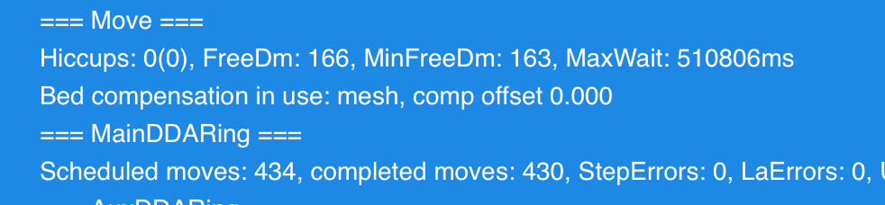
                    So what you have now should work to enable mesh compensation during your print. You can verify if it's enabled by sending M122 in the console and looking for the line that says "compensation in use: mesh"

                    Z-Bot CoreXY Build | Thingiverse Profile

                    tmeryhewundefined 1 Reply Last reply Reply Quote 0
                    • tmeryhewundefined
                      tmeryhew @Phaedrux
                      last edited by

                      @Phaedrux 8b430331-12c7-4c37-bab8-d196a2b0faff-image.png

                      1 Reply Last reply Reply Quote 0
                      • tmeryhewundefined
                        tmeryhew
                        last edited by

                        4e183020-7118-4a5c-9135-73dd4f5f2147-image.png

                        1 Reply Last reply Reply Quote 0
                        • Phaedruxundefined
                          Phaedrux Moderator
                          last edited by

                          Ok so your homeall is using endstop homing for Z instead of the probe.

                          This section

                          G1 H1 Z-305 F360
                          G90
                          G92 Z0
                          

                          Should be replaced by

                          G90 ; absolute position
                          G1 X150 Y150 F6000 ; move probe to bed center
                          G30 ; probe the bed
                          

                          But you haven't shown us your config.g yet, so I'm not actually sure you have a probe configured. What probe do you have? Does it work?

                          https://duet3d.dozuki.com/Wiki/Test_and_calibrate_the_Z_probe

                          Z-Bot CoreXY Build | Thingiverse Profile

                          tmeryhewundefined 1 Reply Last reply Reply Quote 0
                          • tmeryhewundefined
                            tmeryhew @Phaedrux
                            last edited by Phaedrux

                            @Phaedrux

                            ; Configuration file for Duet WiFi (firmware version 3)
                            ; executed by the firmware on start-up
                            ;
                            ; generated by RepRapFirmware Configuration Tool v3.2.3 on Fri Mar 19 2021 21:41:05 GMT-0700 (MST)
                            
                            ; General preferences
                            G90                                                ; send absolute coordinates...
                            M83                                                ; ...but relative extruder moves
                            M550 P"Genesis"                                    ; set printer name
                            
                            ; Network
                            M551 P"shatner1"                                   ; set password
                            M552 P0.0.0.0 S1                                   ; enable network and acquire dynamic address via DHCP
                            M586 P0 S1                                         ; enable HTTP
                            M586 P1 S0                                         ; disable FTP
                            M586 P2 S0                                         ; disable Telnet
                            
                            ; Drives
                            M569 P0 S0                                         ; physical drive 0 goes backwards
                            M569 P1 S0                                         ; physical drive 1 goes backwards
                            M569 P2 S1                                         ; physical drive 2 goes forwards
                            M569 P3 S0                                         ; physical drive 3 goes backwards
                            M584 X0 Y1 Z2 E3                                   ; set drive mapping
                            M350 X16 Y16 Z16 E16 I1                            ; configure microstepping with interpolation
                            M92 X80.00 Y80.00 Z400.00 E105.00                  ; set steps per mm
                            M566 X900.00 Y900.00 Z60.00 E120.00                ; set maximum instantaneous speed changes (mm/min)
                            M203 X12000.00 Y12000.00 Z240.00 E1200.00          ; set maximum speeds (mm/min)
                            M201 X800.00 Y800.00 Z800.00 E250.00               ; set accelerations (mm/s^2)
                            M906 X1200 Y1200 Z1200 E1200 I30                   ; set motor currents (mA) and motor idle factor in per cent
                            M84 S30                                            ; Set idle timeout
                            
                            ; Axis Limits
                            M208 X0 Y0 Z0 S1                                   ; set axis minima
                            M208 X300 Y220 Z300 S0                             ; set axis maxima
                            
                            ; Endstops
                            M574 X1 S1 P"^xstop"                               ; configure active-high endstop for low end on X via pin ^xstop
                            M574 Y1 S1 P"^ystop"                               ; configure active-high endstop for low end on Y via pin ^ystop
                            M574 Z1 S1 P"^zstop"                               ; configure active-high endstop for low end on Z via pin ^zstop
                            
                            ; Z-Probe
                            M950 S0 C"exp.heater3"                             ; create servo pin 0 for BLTouch
                            M558 P9 C"^zprobe.in" H5 F240 T12000               ; set Z probe type to bltouch and the dive height + speeds
                            G31 P500 X-45 Y-7 Z2.345                            ; set Z probe trigger value, offset and trigger height
                            M557 X15:215 Y15:195 S20                           ; define mesh grid
                            
                            ; Heaters
                            M308 S0 P"bedtemp" Y"thermistor" T98801 B4185      ; configure sensor 0 as thermistor on pin bedtemp
                            M950 H0 C"bedheat" T0                              ; create bed heater output on bedheat and map it to sensor 0
                            M307 H0 B0 S1.00                                   ; disable bang-bang mode for the bed heater and set PWM limit
                            M140 H0                                            ; map heated bed to heater 0
                            M143 H0 S100                                       ; set temperature limit for heater 0 to 100C
                            M308 S1 P"e0temp" Y"thermistor" T98801 B4185       ; configure sensor 1 as thermistor on pin e0temp
                            M950 H1 C"e0heat" T1                               ; create nozzle heater output on e0heat and map it to sensor 1
                            M307 H1 B0 S1.00                                   ; disable bang-bang mode for heater  and set PWM limit
                            M143 H1 S250                                       ; set temperature limit for heater 1 to 250C
                            
                            ; Fans
                            M950 F0 C"fan0" Q500                               ; create fan 0 on pin fan0 and set its frequency
                            M106 P0 S0 H-1                                     ; set fan 0 value. Thermostatic control is turned off
                            M950 F1 C"fan1" Q500                               ; create fan 1 on pin fan1 and set its frequency
                            M106 P1 S1 H1 T45                                  ; set fan 1 value. Thermostatic control is turned on
                            
                            ; Tools
                            M563 P0 D0 H1 F0                                   ; define tool 0
                            G10 P0 X0 Y0 Z0                                    ; set tool 0 axis offsets
                            G10 P0 R0 S0                                       ; set initial tool 0 active and standby temperatures to 0C
                            
                            ; Custom settings are not defined
                            
                            ; Miscellaneous
                            M501                                               ; load saved parameters from non-volatile memory
                            M911 S10 R11 P"M913 X0 Y0 G91 M83 G1 Z3 E-5 F1000" ; set voltage thresholds and actions to run on power loss
                            T0                                                 ; select first too
                            
                            1 Reply Last reply Reply Quote 0
                            • Phaedruxundefined
                              Phaedrux Moderator
                              last edited by

                              @tmeryhew said in How is the “Height Map” Used?:

                              ; Z-Probe
                              M950 S0 C"exp.heater3" ; create servo pin 0 for BLTouch
                              M558 P9 C"^zprobe.in" H5 F240 T12000 ; set Z probe type to bltouch and the dive height + speeds
                              G31 P500 X-45 Y-7 Z2.345 ; set Z probe trigger value, offset and trigger height
                              M557 X15:215 Y15:195 S20 ; define mesh grid

                              Ok looks like you have a bltouch. If it's working, you should be able to change the homeall as I indicated above, and it should start using the probe to home Z, and with your slicer start gcode it should home XYZ and then generate a new heightmap and it should be active during the print.
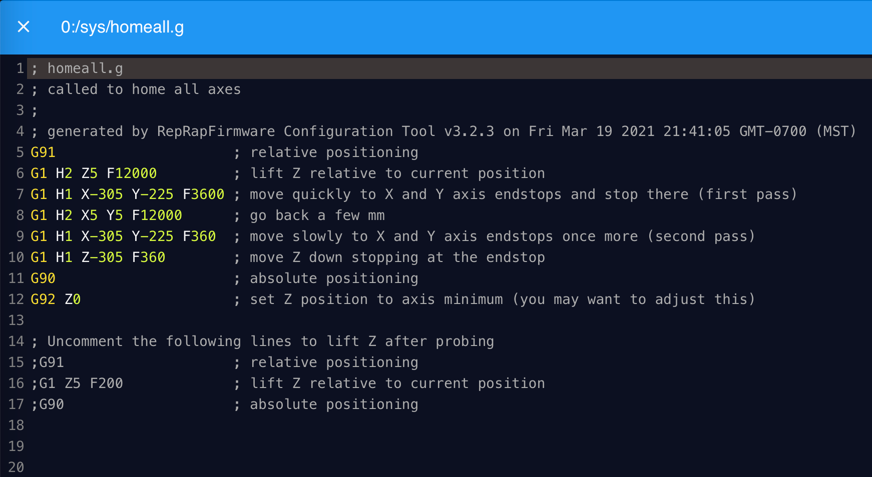
                              Z-Bot CoreXY Build | Thingiverse Profile

                              1 Reply Last reply Reply Quote 1
                              • tmeryhewundefined
                                tmeryhew
                                last edited by

                                ; homeall.g
                                ; called to home all axes
                                ;
                                ; generated by RepRapFirmware Configuration Tool v3.2.3 on Fri Mar 19 2021 21:41:05 GMT-0700 (MST)
                                G91 ; relative positioning
                                G1 H2 Z5 F12000 ; lift Z relative to current position
                                G1 H1 X-305 Y-225 F3600 ; move quickly to X and Y axis endstops and stop there (first pass)
                                G1 H2 X5 Y5 F12000 ; go back a few mm
                                G1 H1 X-305 Y-225 F360 ; move slowly to X and Y axis endstops once more (second pass)
                                G90 ; absolute positioning
                                G1 X150 Y110 F6000 ; move probe to bed center
                                G30 ; probe the bed

                                ; Uncomment the following lines to lift Z after probing
                                ;G91 ; relative positioning
                                ;G1 Z5 F200 ; lift Z relative to current position
                                ;G90 ; absolute positioning

                                1 Reply Last reply Reply Quote 1
                                • tmeryhewundefined
                                  tmeryhew
                                  last edited by

                                  And to clarify, yes it appears to be working. I can definitely generate a height map. Are there other things I should be looking for to confirm its working?

                                  Other than obviously not crashing into the bed.

                                  1 Reply Last reply Reply Quote 0
                                  • Phaedruxundefined
                                    Phaedrux Moderator
                                    last edited by Phaedrux

                                    The best way to test is to print a first layer test print twice. Once with G29 in the start gcode, and again with G29 S0 in the start gcode to disable it.

                                    Something like this file works well.

                                    bedlevel_nozzle_0.4_200x200-0.3-0.8.stl

                                    I think the missing piece of the puzzle in your case was not using the probe to home z.

                                    Z-Bot CoreXY Build | Thingiverse Profile

                                    tmeryhewundefined 2 Replies Last reply Reply Quote 1
                                    • tmeryhewundefined
                                      tmeryhew @Phaedrux
                                      last edited by

                                      @Phaedrux thank you so much. You guys really know your stuff. I'll go ahead and work on this right now.

                                      How can I save/export all of my settings as a JSON once I have it dialed in?

                                      Phaedruxundefined 1 Reply Last reply Reply Quote 0
                                      • Phaedruxundefined
                                        Phaedrux Moderator @tmeryhew
                                        last edited by

                                        @tmeryhew said in How is the “Height Map” Used?:

                                        How can I save/export all of my settings as a JSON once I have it dialed in?

                                        You can back up the .g files in the /sys folder of your SD card.

                                        From DWC, go to the system tab, there is a check box above the list of files, click it to select all the files, then right click on the file list area and select "Download as zip" to save all the files there as a zip file on your computer.

                                        Then if you ever needed to restore the configuration to that point you could upload that zip file again to the system tab. Or extract it and upload a particular file you want.

                                        Z-Bot CoreXY Build | Thingiverse Profile

                                        tmeryhewundefined 1 Reply Last reply Reply Quote 1
                                        • tmeryhewundefined
                                          tmeryhew @Phaedrux
                                          last edited by

                                          @Phaedrux c5451534-faad-440c-bd5b-334a270a7162-image.png

                                          I've gone in and made the changes you describe. I am running the file you sent as we speak. I sent M122 and this was the result.

                                          Should my "comp offset" be 0.000? Does this mean anything?

                                          1 Reply Last reply Reply Quote 0
                                          • Phaedruxundefined
                                            Phaedrux Moderator
                                            last edited by

                                            No the important thing is that it indicates the mesh is loaded.

                                            It should be moving the Z axis to compensate for the surface of the bed now.

                                            Z-Bot CoreXY Build | Thingiverse Profile

                                            1 Reply Last reply Reply Quote 0
                                            • First post
                                              Last post
                                            Unless otherwise noted, all forum content is licensed under CC-BY-SA