Duet3D Logo Duet3D
    • Tags
    • Documentation
    • Order
    • Register
    • Login

    Polar Printer Steps/Degree?

    Scheduled Pinned Locked Moved
    General Discussion
    5
    49
    2.9k
    Loading More Posts
    • Oldest to Newest
    • Newest to Oldest
    • Most Votes
    Reply
    • Reply as topic
    Log in to reply
    This topic has been deleted. Only users with topic management privileges can see it.
    • Phospherusundefined
      Phospherus @dc42
      last edited by

      @dc42

      Did the above provide any insight?

      1 Reply Last reply Reply Quote 0
      • shadiundefined
        shadi @Phospherus
        last edited by shadi

        @phospherus Hi can you please help me it seems i have the same issue my design is that y turntable plate and x is R should that work if i put Y value 2.5 is this what has been discussed in your subject ? and what about X value then ? M92 X?? Y2.5 is this how m92 should look like but i just would like to mention if that can work with SKR1.4 that has repaprfirmware on it ? I slice using Cura the output file from cura is linear coordinate and I assume the firmware should convert it to polar

        Phospherusundefined 1 Reply Last reply Reply Quote 0
        • Phospherusundefined
          Phospherus @shadi
          last edited by Phospherus

          @shadi
          If you are using reprap on skr as far as I know the values should be the same but can not swear to that as I use OEM boards.

          Your X axis is non rotational I assume so it would be figured by pulley teeth and step angle

          So 200 steps = 1 revolution (360degress / 1.8 degrees per step). multiplied by micro stepping factor of 16 will = 3200

          Pitch of the belt for GT2 is 2mm. Multiplied by the number of teeth on motor pulley. We will use 20. So 2 x 20 = 40

          Then 3200/40 = 80 steps per mm for a 1.8 degree motor with GT2 belt and a 20 tooth pinion.

          For the rotational bed we need to know what gear reduction you are using if any. The step angle of your stepper and the following should tell you what your value would be. If your not running 20:90 gear reduction then my value will not work for you.

          The formula CNCModeller provided is.

          1.8 Deg/step at the motor x 20 / 90 = 0.4 deg/step at the bed.

          1/0.4 = 2.5 steps/Deg at the bed.

          1.8 degree is the step angle of the stepper motor multiplied by my gear ratio.

          20/90 is my gear ratio. Pinion or drive gear divided by my driven gear which is 90 which comes to 0.4

          0.4 is the fraction of a degree at the bed through the gear reduction.

          So we want to know how many steps to make a degree with the reduction. So you divide 1 degree by the steps at the bed which is the 2.5 steps to get 1 degree at the bed.

          Then you must take the last value and multiply it by your step multiplier mine is 2.5 X 16 = 40. That is what is enter for your Y in the config.

          I hope this helps.

          And thank you CNCModeller for the original formula.

          shadiundefined 1 Reply Last reply Reply Quote 0
          • shadiundefined
            shadi @Phospherus
            last edited by shadi

            This post is deleted!
            Phospherusundefined 1 Reply Last reply Reply Quote 0
            • Phospherusundefined
              Phospherus @shadi
              last edited by

              @shadi

              Just tell me how many teeth are on the gear on the stepper motor and how many teeth are on the big gear driven by the stepper motor.

              shadiundefined 1 Reply Last reply Reply Quote 0
              • dc42undefined
                dc42 administrators @Phospherus
                last edited by dc42

                @phospherus, I don't have a polar printer, but I did some firmware tests in polar mode before I released 3.3beta3 and the motor movements appeared correct to me. Please can you re-test that print using the 3.3beta3 release.

                Duet WiFi hardware designer and firmware engineer
                Please do not ask me for Duet support via PM or email, use the forum
                http://www.escher3d.com, https://miscsolutions.wordpress.com

                shadiundefined 1 Reply Last reply Reply Quote 0
                • shadiundefined
                  shadi
                  last edited by

                  @phospherus 16 teeth on the small gear and 258 teeth on the large gear, i just want highlight that the drawing is skewed with round edges,

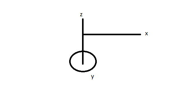
                  I mean this machine should move Y= Theta, and X= R where are the SQRT (XX + YY)

                  is that correct ?

                  1 Reply Last reply Reply Quote 0
                  • shadiundefined
                    shadi @Phospherus
                    last edited by

                    @phospherus 16teeth on the small gear and 258 teeth on the large one

                    1 Reply Last reply Reply Quote 0
                    • shadiundefined
                      shadi @dc42
                      last edited by

                      @dc42 Hi I just tested different reprapfirmware version on my SKR1.4 almost all have the same behavior which indicates the issue is not in the firmware however in the configurations, can you advise the possible configurations ?

                      Phospherusundefined 1 Reply Last reply Reply Quote 0
                      • Phospherusundefined
                        Phospherus @shadi
                        last edited by

                        @shadi

                        Ok with that gear ratio at 16X your y axis steps per degree should be M92 Y14.33

                        @dc42 I will test again as soon as I have a chance. I did however get my BLtouch and mesh bed setup on 3.2.2 on the polar as a delta using radius and seems to work very well.

                        shadiundefined 2 Replies Last reply Reply Quote 0
                        • shadiundefined
                          shadi @Phospherus
                          last edited by shadi

                          @phospherus said in Polar Printer Steps/Degree?:

                          gain as soon as I have a chance. I did however get my BLtouch and mesh bed setup on 3.2.2 on the polar as a delta using radius and seems to work very well.

                          @dc42 In my case actually Y plate is turntable and X and Z are both moving as they are located on the table, did you test the same and it works ? if possible to share the config.g that you have tested at ?polar-machine-example.png

                          have you tested for this design ?

                          1 Reply Last reply Reply Quote 0
                          • shadiundefined
                            shadi @Phospherus
                            last edited by shadi

                            This post is deleted!
                            Phospherusundefined 1 Reply Last reply Reply Quote 0
                            • Phospherusundefined
                              Phospherus @shadi
                              last edited by Phospherus

                              @shadi

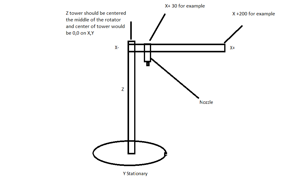
                              Ok on a polar printer the center of the turn bed or rotating plater is 0,0 for the X and Y axis. On your design with the z tower being in the middle and rotating you will have to measure from the center of the tower out to the closest position to the tower that the x axis can get to. I would measure from center of tower to max X position and home to the + instead of minus. But your lowest X position will be the distance from center of tower to the nozzle.

                              Also on a polar with the bed rotating the y axis goes in the clockwise direction for plus. On your design the Z and X would need to go counter clockwise.

                              As for steps per mm for the X. I need to know belt pulley teeth count on stepper and belt pitch to help with that.

                              I hope I explained this well enough.

                              Polar.png

                              shadiundefined 1 Reply Last reply Reply Quote 0
                              • shadiundefined
                                shadi @Phospherus
                                last edited by shadi

                                This post is deleted!
                                Phospherusundefined 2 Replies Last reply Reply Quote 0
                                • Phospherusundefined
                                  Phospherus @shadi
                                  last edited by Phospherus

                                  @shadi

                                  When looking as the Z,X Gantry it should rotate counterclockwise.

                                  Please post your config.

                                  shadiundefined 1 Reply Last reply Reply Quote 0
                                  • Phospherusundefined
                                    Phospherus @shadi
                                    last edited by

                                    @shadi

                                    For your M92 X100 Y14.33 Z401 E84

                                    1 Reply Last reply Reply Quote 0
                                    • shadiundefined
                                      shadi @Phospherus
                                      last edited by shadi

                                      This post is deleted!
                                      Phospherusundefined 2 Replies Last reply Reply Quote 0
                                      • Phospherusundefined
                                        Phospherus @shadi
                                        last edited by Phospherus

                                        @shadi

                                        Where is your X axis Endstop is it by the tower or at the end of arm?

                                        If you X homes to min and is near tower. Then you need to to home to the switch and in your homing file do a G92 X105 to set the X at the homing switch to X105. but you will have to change your M208 parameter.

                                        ; Axis Limits
                                        M208 X105 Y0 Z0 S1 ; set axis minima
                                        M208 X445 Y360 Z400 S0 ; set axis maxima

                                        Also like I said rotating bed or Y axis normally go clockwise. since you are rotating X you need it to go counterclockwise.

                                        shadiundefined 1 Reply Last reply Reply Quote 0
                                        • shadiundefined
                                          shadi @Phospherus
                                          last edited by

                                          @phospherus Yes it home at lower end that is right but i did not yet fixed the switch

                                          Phospherusundefined 1 Reply Last reply Reply Quote 0
                                          • Phospherusundefined
                                            Phospherus @shadi
                                            last edited by

                                            @shadi

                                            The X arm itself does not need to be the nozzle itself needs to be perfectly centered.

                                            1 Reply Last reply Reply Quote 0
                                            • First post
                                              Last post
                                            Unless otherwise noted, all forum content is licensed under CC-BY-SA