Ender 6 fault temps in Heaters Hotend and Bed
-
 Dear People I need your help
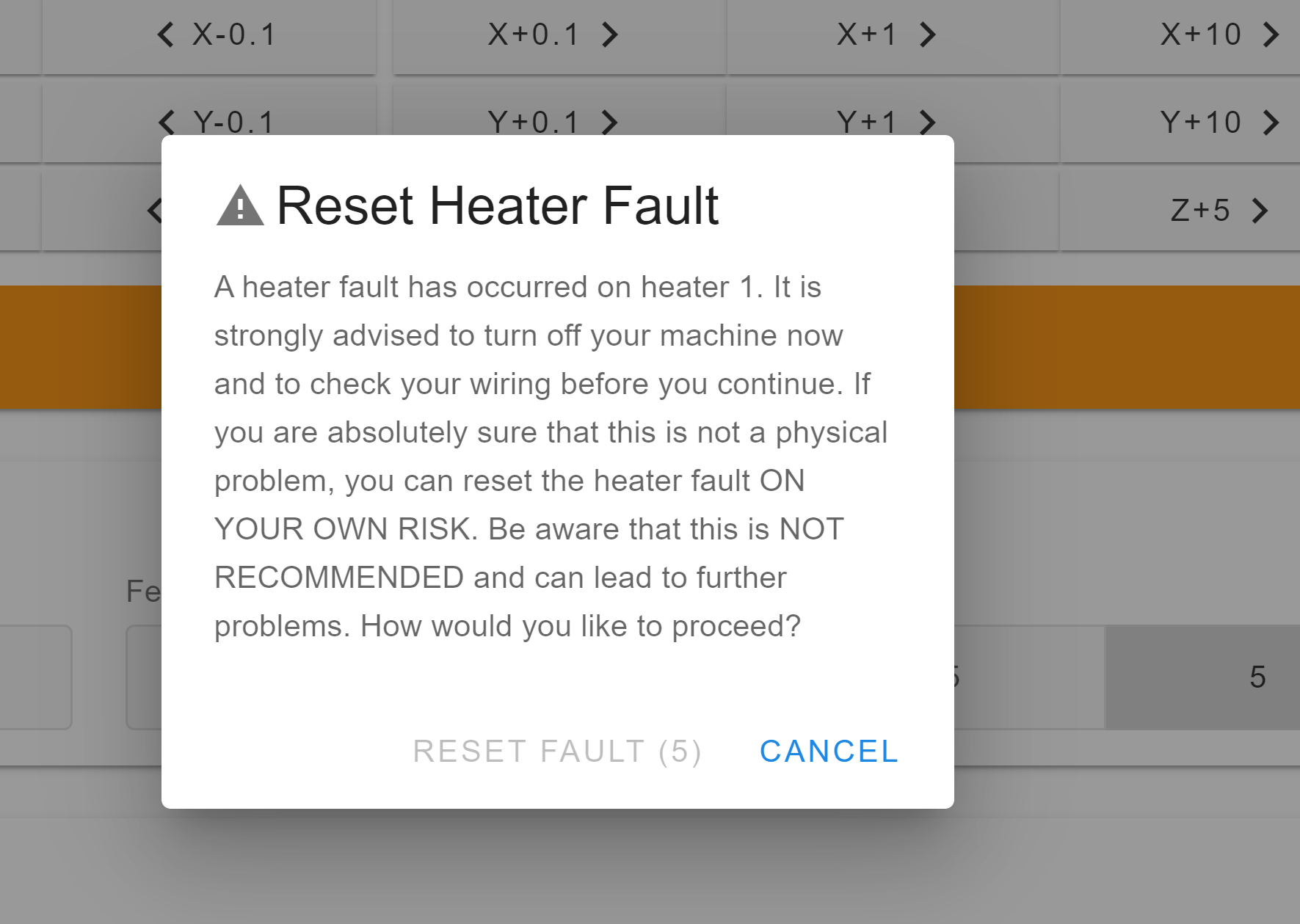
I have a fault error in the Heater readings from my sensor, shows 338.7c in the hotend and -15.9 in the Bed. It is my first time wiring and booting the Mini 5 + mainboard. Recently purchased.
I have installed all the wires and did the setup for the wifi succesufully but now I have this error. I have double checked the wiring and everything seems ok.
My printer is an Ender 6 with the Duet Mini 5+. I have followed the instructions related to the Ender 3, is very similar to Ender 6 in the wiring. Probably I need to change something in G-Code, but for sure I am missing something here. Did you have any tips, I am really new installing all this stuff and modifying my Ender 6 but I am fast student
")
Thank you

-
@javcab One possibility could be you have the wrong B value for your themister. Or you have bad connection, use multimeter to see if your getting the right resistance.
Use the </> to paste in your config.g file into your reply.
-
Your heater section in config.g should look something like this:
; Heaters
M308 S0 P"temp0" Y"thermistor" T98801 B4185        ; configure sensor 0 as thermistor on pin temp0
M950 H0 C"out0" T0                                 ; create bed heater output on out0 and map it to sensor 0
M307 H0 B0 S1.00                                   ; disable bang-bang mode for the bed heater and set PWM limit
M140 H0                                            ; map heated bed to heater 0
M143 H0 S120                                       ; set temperature limit for heater 0 to 120C
M308 S1 P"temp1" Y"thermistor" T98801 B4185        ; configure sensor 1 as thermistor on pin temp1
M950 H1 C"out1" T1                                 ; create nozzle heater output on out1 and map it to sensor 1
M307 H1 B0 S1.00                                   ; disable bang-bang mode for heater  and set PWM limit
M143 H1 S240                                       ; set temperature limit for heater 1 to 240C
The thermistor values for the Creality thermistors is
T98801 B4185If you have values far off from those that might explain the whacky temps. -
@phaedrux Thank you very much for your reply.
I have the configuration thta you sent. But still the problem. I have the feeling that is something to do with the wiring but I have checked 10 times and did some tests removing fans and jumpers. But I am not sure if this helps in my research to find the problem.DId you think that the Bondtech DDX v3 is not a problem of compatibility? This version of Bondtech has an special wire configuration for Creality Ender 6. They send an extension with the cable prepared to connect in the sprayboard to avoid the motors runnning in reverse.
Until now I didnt try to move any of the motors or the nozzle, still I dont know if the other settings are right but this another steps I will check until I discover and resolve my problem with the sensor heater
You in Duet are really good, thank you
-
Its possible they are using a different thermistor in the ender6 than in their other printers, but as far as I can see it's a basic 100k NTC.
Try T100000 B3950
-
@phaedrux No luck, went up the temps a little bit more to 1512 Celsius.
I dont have more clues

Anything you need to help you to help me I can do it.
If you have any idea what could be probably the problem I can test or install, whatever, just dont forget me")
Cheers
Javier -
Photo of the thermistor and the wiring connection?
@javcab said in Ender 6 fault temps in Heaters Hotend and Bed:
DId you think that the Bondtech DDX v3 is not a problem of compatibility? This version of Bondtech has an special wire configuration for Creality Ender 6. They send an extension with the cable prepared to connect in the sprayboard to avoid the motors runnning in reverse.
Does the thermistor go through that as well?
-
@phaedrux Sorry for the double post.
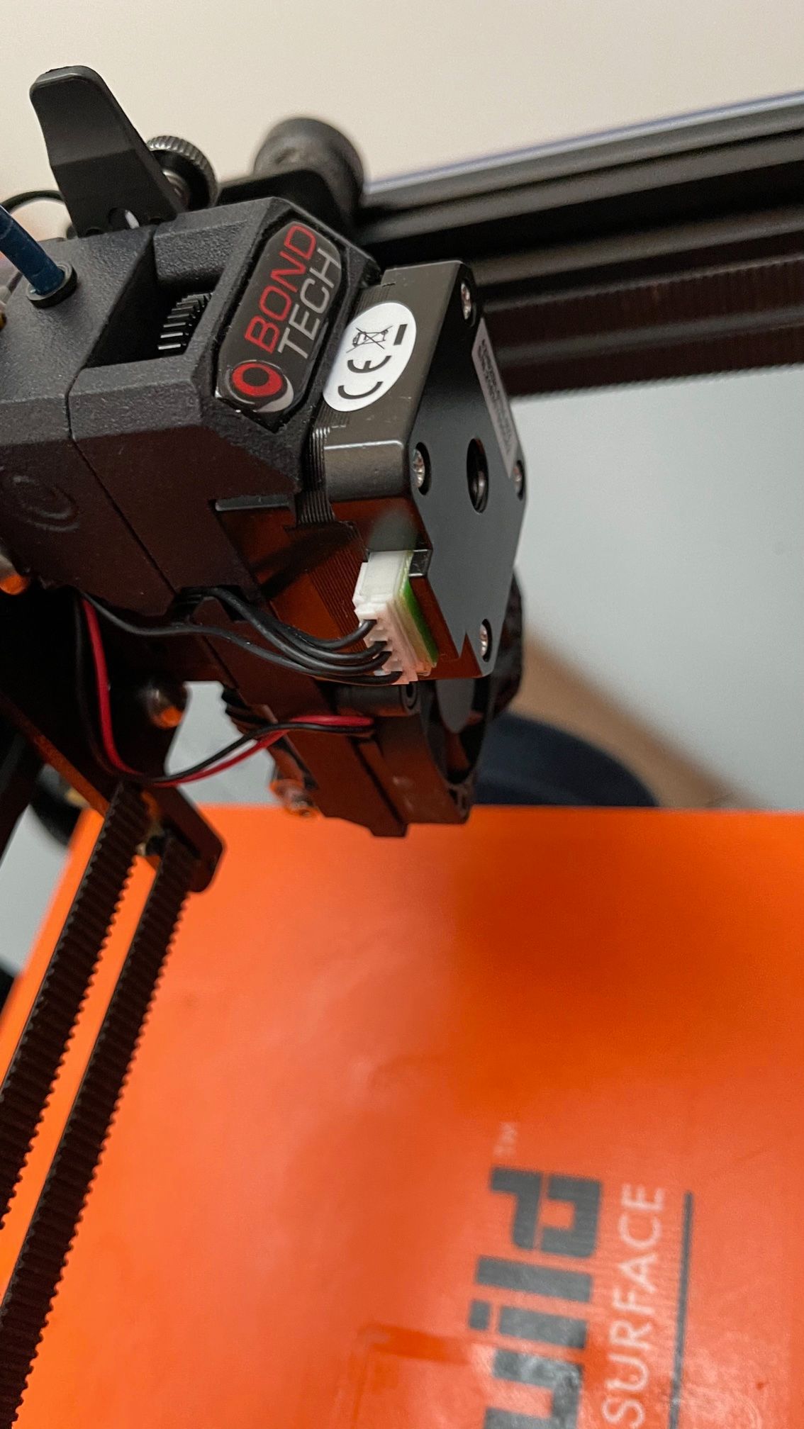
Here are the photos for the wiring.
First photo shows the wires coming out from the extruder Bondtech DDX v3. This cable has the function to connect the right cables to the original cable from Creality in the sprayboard
Also please find attached the image from the site Bondtech explaining the wiring for the extruder
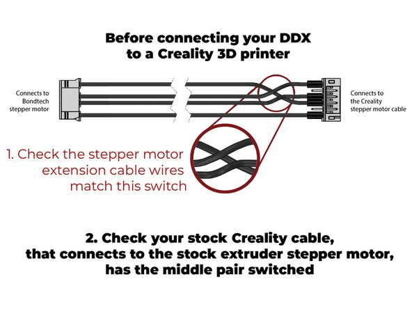
Here is the link for the site too: https://support.bondtech.se/Guide/02.+Installing+DDX+On+Creality+Ender-3/64
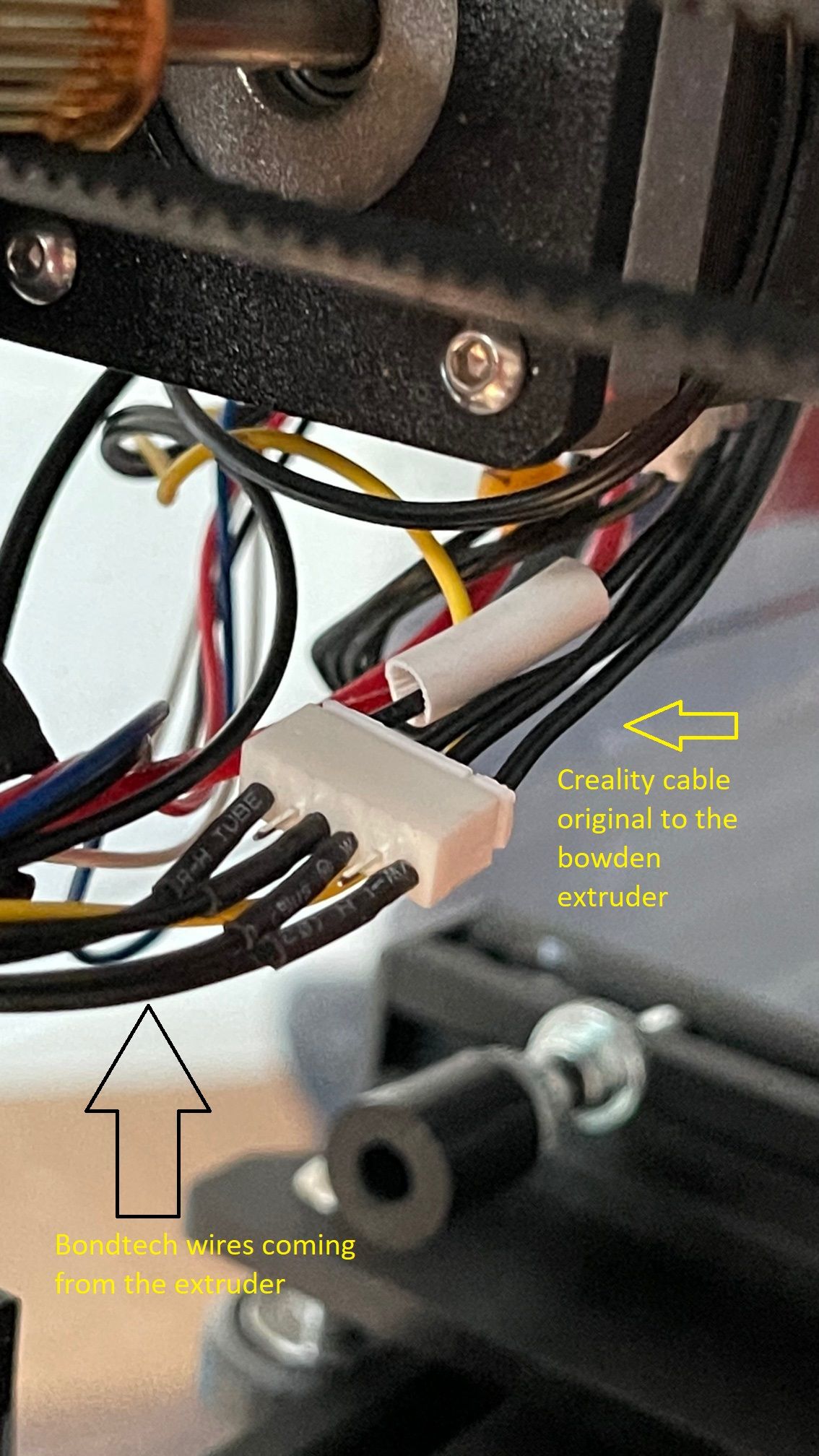
Then follows the next photo with the cable coming from the Bondtech extruder in the original cable from Creality, normally this will go to the bowden extruder but now is used as advised in the Bondtech site to connect to the original mainboard from Creality. See photo
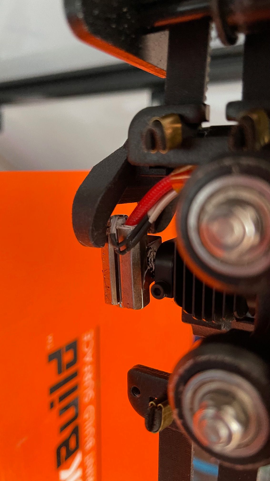
Also here is the photo for the thermistor, they are the stock thermistor from Creality, no changes here in the wiring.
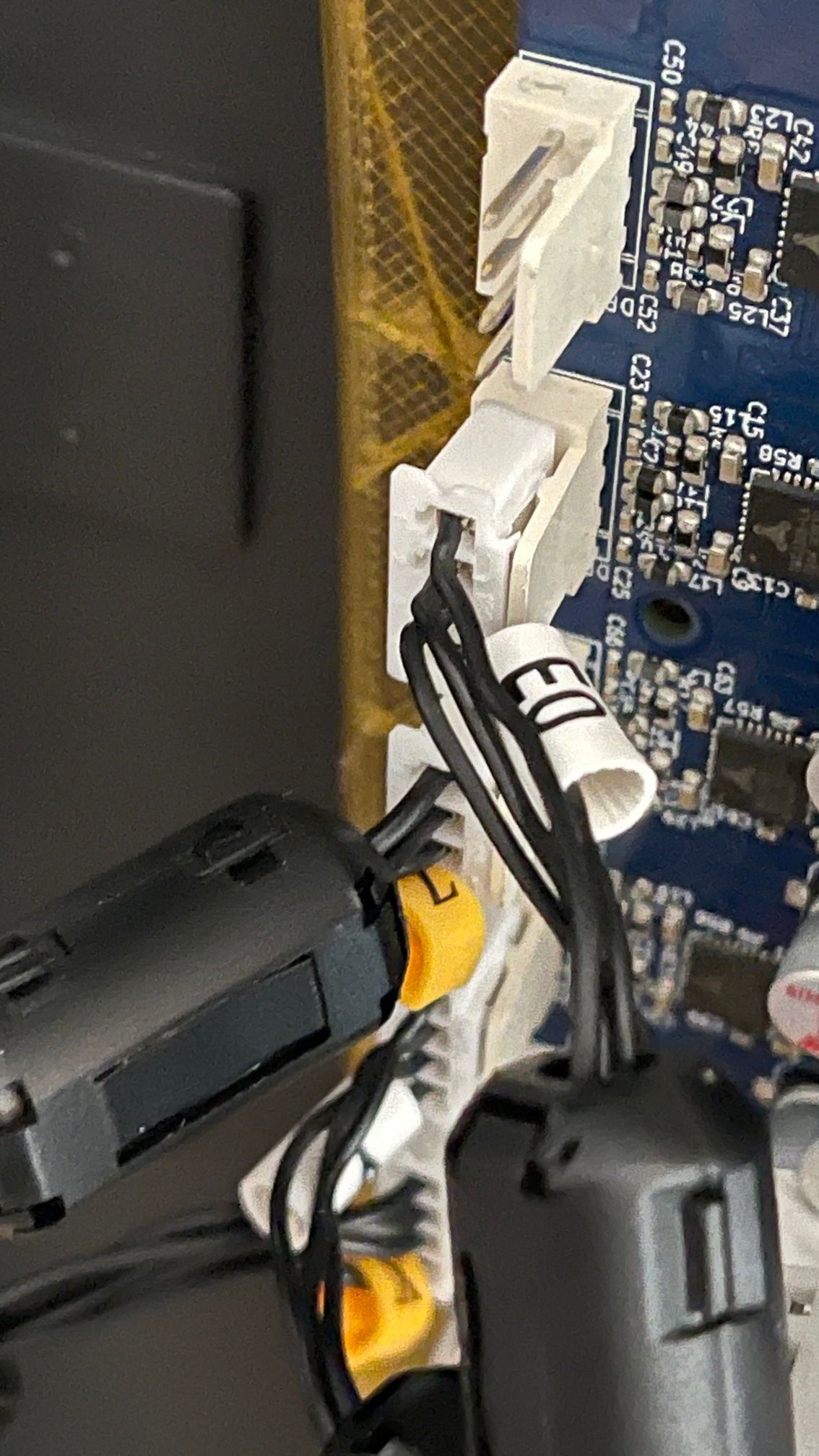
Last photo is the wires coming to the Duet Mini 5
Notice: The fan for the extruder runs all the time, even when is not connected the cable for the fan in the mainboard Duet. This is normal?
Also, before this all changes, the Bondtech and the Printer was working correctly, was no issues of any type. Did you think that I need to connect the Bondtech Extruder directly to the Duet mini using other position for the wires?
Really appreciate your time and help to read this, thank you
-
@javcab sorry I forgot to add the las photo
-
Is that a genuine bondtech hotend kit? Is that a Mosquito hotend? They may be using different thermistor than the stock creality stuff?
For the motor connection you should find the phase pairs yourself and then connect it accordingly. Any cross over that they recommend doing may not apply here. Best to find the pairs empirically.
Notice: The fan for the extruder runs all the time, even when is not connected the cable for the fan in the mainboard Duet. This is normal?
If the fan is running all the time and not connected to the duet it must be connected directly to a power supply?
-
@phaedrux Would you mind sharing how you wired the "det" and "pwm" wires from the Ender 6 to the Duet board?
-
@ddrake Do you mean to ask me, or @javcab ?
@ddrake said in Ender 6 fault temps in Heaters Hotend and Bed:
"det" and "pwm" wires from the Ender 6
Not sure which wires those are. Can you elaborate?
-
@phaedrux that was meant for @javcab
Sorry
The "det" one is a 4-wire, which I believe is where the BLTouch, and whatever else is on the breakout board, gets its power from.
The "pwm" wire is a 2-wire, with what looks like a neutral and a 2nd wire.
I can use a meter to see where they actually go, but I'm not sure about where on the Duet they would go. There is literally no information online regarding this.
-
Well if you can identify which wire goes for which piece of hardware we can probably figure out where to plug it in on the Duet based on it's purpose.
-
This post is deleted! -
Not really sure what I'm looking at. Photo of the actual board for context?
Shared grounds are a bit problematic for the Duet when it comes to fans and heaters because the duet switches the PWM signal on the ground side, so fans and heaters will need their own ground wire. They can share the same supply voltage though as long as it can handle the combined current.
Any signal wires would need to go to the signal pin for that device, endstops, probe trigger signal.
-
Edited: I will upload photos, and re-do my wiring diagram, because it was wrong.
@phaedrux I believe many things in the upper portion, like X and Y endstops, extruder, extruder fan, parts cooling fan, filament runout detector, and BLTouch that have one, all share a common ground.
looks like the BLTouch's yellow and power are tied into the two pwm wires. The yellow, black, and blue wires on the BLTouch are all grounded conductors, but I'm assuming the blue maybe a tx/rx. The filament runout has a power, ground, and a yellow wire, that is also a grounded conductor.
I hope you can help me. Thanks a lot, either way.
-
Ignore the text
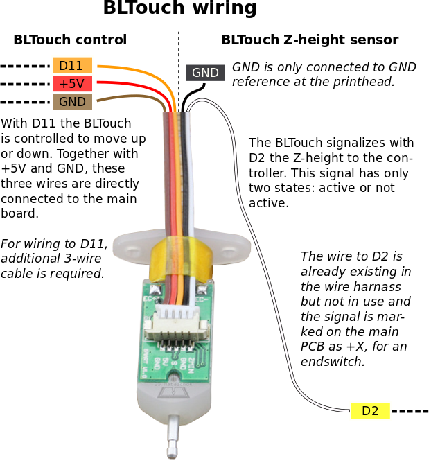
Black and brown are grounds. White is signal for trigger. Red is 5v power in. Yellow is PWM control for pin.
-
@phaedrux That is an older BLTouch. The newer ones have a QR code on the bottom. Mine is v3.1, and is a bit different. I believe the +5v and GND are swapped, and it can also do +3.3v logic automatically, without needing modifications.
The breakout board seems new to the latest versions of the Ender 6, as my breakout board has a date of 3/31/21. I'm still mapping out the connections to the breakout board and the different connections coming out of it, and I'll post what I find, and if I work it out, what the solution is, as nobody seems to want to share what they ended up doing.
-
Yeah proprietary breakout boards are tricky because they often used shared ground which is problematic with electronics that switch on the negative side.