Duet 2 Wifi Bltouch isn't working.
-
Hello people on the internet,
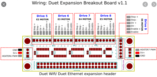
I have a problem with the duet 2 wifi V3.2.2 it has a expansion breakout board V1.1 and a bltouch V3.1.
When I turn on the duet 2 wifi the bltouch does the self test but, when I send the M280 Px S10 code nothing happens. Also the M280 Px S120 code doesn't work. I have changed many things in my config code but nothing seems to make my bltouch work.Also I have a breakout expansion board, and I have the yellow cable of the bltouch connected with Heater7 PWM pin on the breakoutboard, and the red cable of the bltouch connected to the 5V+ of the breakout board, and the brown cable of the bltouch connected on the GND of the breakoutboard.
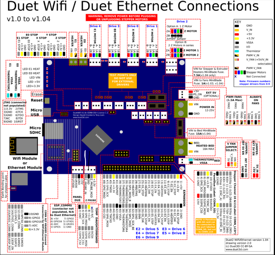
I have the White cable of the Bltouch connected on the Z_probe_in and the black cable of the bltouch connected on GND of the Z probe.
Here is the config file
; Configuration file for Duet WiFi (firmware version 3)
; executed by the firmware on start-up
;
; generated by RepRapFirmware Configuration Tool v3.2.3 on Thu Apr 01 2021 12:58:22 GMT+0200 (Midden-Europese zomertijd); General preferences
G90 ; send absolute coordinates...
M83 ; ...but relative extruder moves
M550 P"Olga" ; set printer name; Network
M551 P"26627243" ; set password
M552 S1 ; enable network
M586 P0 S1 ; enable HTTP
M586 P1 S0 ; disable FTP
M586 P2 S0 ; disable Telnet; Drives
M569 P0 S1 ; physical drive 0 goes forwards
M569 P1 S1 ; physical drive 1 goes forwards
M569 P2 S0 ; physical drive 2 goes forwards
M569 P3 S1 ; physical drive 3 goes forwards
M584 X5 Y6 Z7 E3 ; set drive mapping
M350 X1 Y1 Z1 I0 ; configure microstepping without interpolation
M350 E16 I1 ; configure microstepping with interpolation
M92 X101.85916357881 Y76.87484044 Z77.28312866 E420.00 ; set steps per mm
M566 X30.00 Y30.00 Z2.50 E120.00 ; set maximum instantaneous speed changes (mm/min)
M203 X8000.00 Y8000.00 Z2000.00 E1200.00 ; set maximum speeds (mm/min)
M201 X30.00 Y30.00 Z2.50 E250.00 ; set accelerations (mm/s^2)
M906 X400 Y400 Z400 E800 I70 ; set motor currents (mA) and motor idle factor in per cent
M84 S30 ; Set idle timeout; Axis Limits
M208 X0 Y0 Z0 S1 ; set axis minima
M208 X2400 Y1400 Z950 S0 ; set axis maxima; Endstops
M574 X1 S1 P"xstop" ; configure active-high endstop for low end on X via pin xstop
M574 Y1 S1 P"ystop" ; configure active-high endstop for low end on Y via pin ystop
M574 Z1 S2 ; configure Z-probe endstop for low end on Z; Z-Probe
M558 P9 C"^zprobe.in" H5 F100 T2000
M950 S0 C"exp.heater7"
G31 X20 Y0 Z3.3 P25;Heaters
M308 S0 P"bedtemp" Y"thermistor" T100000 B4138 ; configure sensor 0 as thermistor on pin bedtemp
M950 H0 C"bedheat" T0 ; create bed heater output on bedheat and map it to sensor 0
M307 H0 B1 S1.00 ; enable bang-bang mode for the bed heater and set PWM limit
M140 H0 ; map heated bed to heater 0
M143 H0 S120 ; set temperature limit for heater 0 to 120C
M308 S1 P"e0temp" Y"thermistor" T100000 B4138 ; configure sensor 1 as thermistor on pin e0temp
M950 H1 C"e0heat" T1 ; create nozzle heater output on e0heat and map it to sensor 1
M307 H1 B0 S1.00 ; disable bang-bang mode for heater and set PWM limit
M143 H1 S280 ; set temperature limit for heater 1 to 280C
M307 H1 R2.698 C89.1 D4.55 S1.00 V24.0; Fans
M950 F0 C"fan0" Q500 ; create fan 0 on pin fan0 and set its frequency
M106 P0 S1 H1 T45 ; set fan 0 value. Thermostatic control is turned on
M950 F1 C"fan1" Q500 ; create fan 1 on pin fan1 and set its frequency
M106 P1 S0 H-1 ; set fan 1 value. Thermostatic control is turned off; Tools
M563 P0 D0 H1 F0 ; define tool 0
G10 P0 X0 Y0 Z0 ; set tool 0 axis offsets
G10 P0 R0 S0
M563 P1 F0
G10 P1 X0 Y0 Z0
G10 P1 R0 S0
; set initial tool 0 active and standby temperatures to 0C
; Custom settings are not defined,
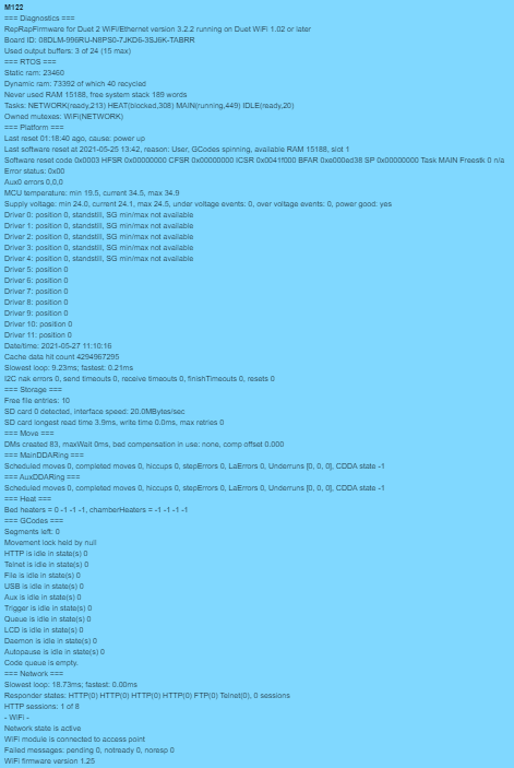
Diagnostics
If somebody has a idea what is wrong or could be wrong please answers.
Thanks in advance
-
@fireghost2013 When you use the expansion breakout board, it acts similarly to the Duex5 expansion board. That is, the operation of Heater 7 PWM is inverted. So change your M950 line to:
M950 S0 C"!exp.heater7"See this thread for a similar setup (and I still need to add a note to the BoB page): https://forum.duet3d.com/topic/22225/bltouch-not-responding-to-code
Ian
-
@droftarts
Thank you, that was the problem, thank you very much you are amazing