Duet 3 mini external trigger problems
-
@droftarts I just took a closer look at my floating pin theory and noticed the duet 2 had a 1K pullup while the 3 mini has a 27k pullup.
Any reasons NOT to connect a 10k resistor between 3.3V and IN to try to rule this idea out? -
@benecito said in Duet 3 mini external trigger problems:
Any reasons NOT to connect a 10k resistor between 3.3V and IN to try to rule this idea out?
It is safe to do that. You can go down to 1K if you need to.
-
@dc42 Thanks! I'll try it and get back to you.
-
It seems the 10k pullup resistor solved the problem (for now?!) But what I still don't get is, the other printer that had the exact same problem, but it disappeared at some point without any changes.
I'm a little worried I didn't solve the problem and the actual cause is something else. Also I'd like to understand the why and if there is another solution to it then wiring lots of resistors as it is a pain in the a** to do.
Can it simply be that the duet 3's pullup is too big?
-
@benecito the problem is that wires connecting normally-open endstop switches are susceptible to capacitive interference pickup, in particular from nearby stepper motor cables but to a lesser extent from heater and fan cables. You can mitigate this to some extent by using lower value pullup resistors. A better solution is to change to normally-closed endstop switches if possible, or to use shielded cable to connect the normally-open endstop switch.
We used low value pullup resistors and LEDs on the Duet WiFi, but unfortunately some optical and Hall effect endstops can't handle such low value pullup resistors. That's why we use higher value pullup resistors on the Duet 3.
-
@dc42 said in Duet 3 mini external trigger problems:
A better solution is to change to normally-closed endstop switches if possible, or to use shielded cable to connect the normally-open endstop switch.
You happen to know any switch like the D2LS-11? I already had a hard time finding these and don't have a lot more room available.
Just did some more research and had another idea: is it possible to configure the switch so I can connect it between 3.3/5V and IN? Probably won't make much sense as I'd need a pulldown instead of a pullup which I can get rid of that easily, but found some information suggesting this way round the signal change is / can be greater.
-
@dc42
I'm sorry I have to get back to you. Just finished the second printer (exact same configuration) with the 10k pullups and the problem just showed back up.How can it be one is working / seems to work while the other one does not? Can it be something else?
-
I ordered an oscilloscope the other day to narrow it down and will see.
Does it make a difference if I configure it either way?
M950 J1 C"^!io2.in"
M581 T3 P1 S1 R0
or
M950 J1 C"^io2.in"
M581 T3 P1 S0 R0
I guess one triggers when the signal is no longer high, the other one when it gets low? What are the trigger levels for the 3 mini?
-
Thanks to @LeckieTech over at Limit Switch False Triggering Duet 3 Mini I got the Idea of using a capacitor.
NC switches can't be done, and shielded wiring would be a pain in the a** to do.Just did some comparison with pullups and capacitors. Here are the results using a 1.5k resistor and a 0,1 µF capacitor:
- the input triggers at around 1.2V
- bare board: 3.17V average with drops down to 1.9V (close enough to 1.2V)
- with capacitor drops only go down to 2.8V
- pullup to 3.3V gets the average to 3.3V with drops to 2.5V
an additional capacitor keeps drops to 2.9V - pullup to 5V gets the average to 4.7V with drops to 4.0V
an additional capacitor keeps drops to 4.3V
Like mentioned above the 10k pullup did not keep false triggering. The 1.5k did 99.99% of time.
- is there a reason not to wire a pullup to 5V
- is there a reason why on the 3 mini for the IO's there are pads for capacitors but they are supposed to be not populated?
-
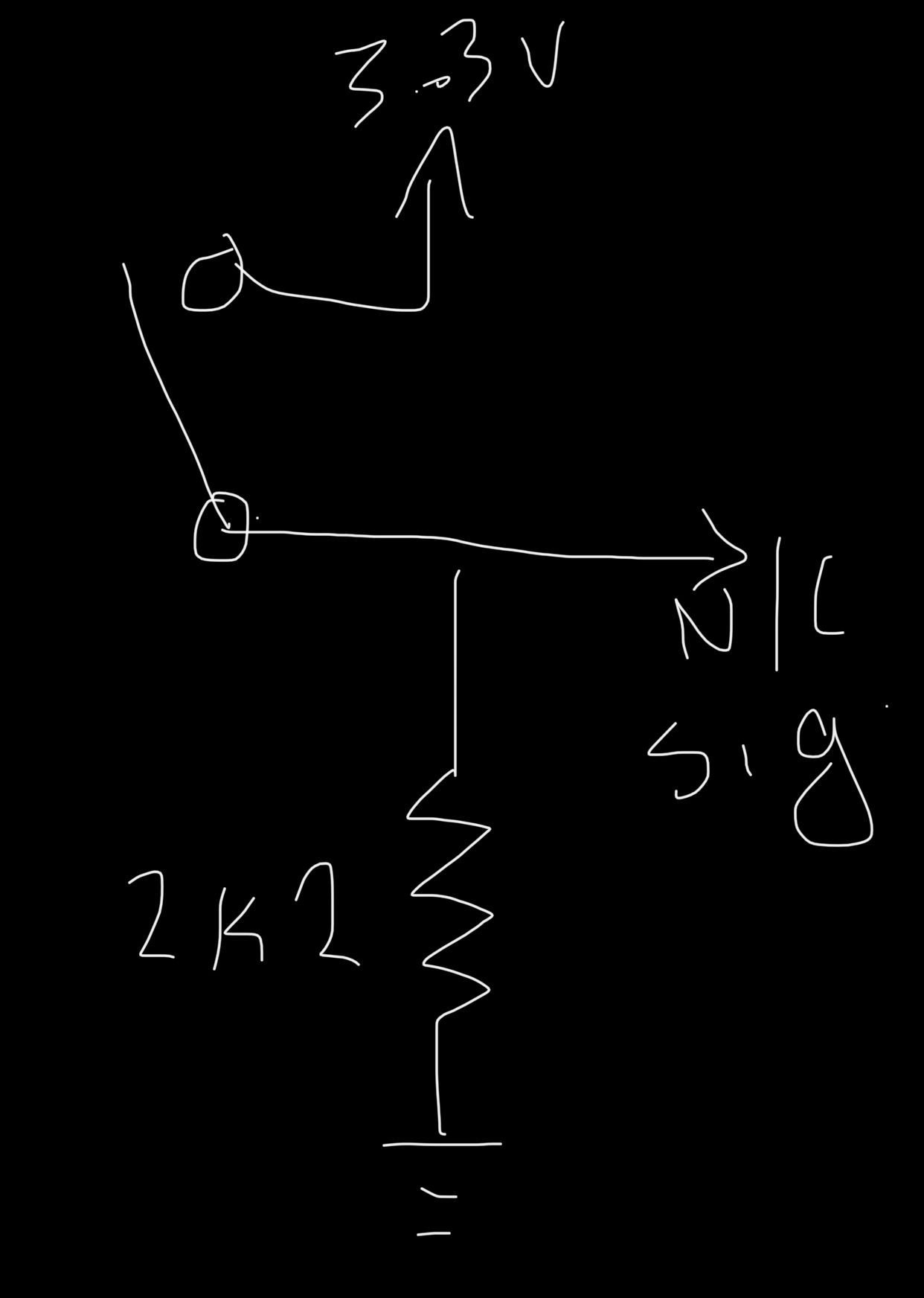
@benecito I used a 0.01uf ceramic cap between gnd and signal and a 4.7k resistor between signal and 3.3v. Watch your cap size though, too big and it will damage the switch over time and also delay the triggering which could be a problem for Z. Ive followed @dc42 's advice to wire all my triggers to N/C, but like you, I have one trigger that is just too much of a pain to replace the switch to gain a N/C contact. So I wired it like this (sorry for the finger painting):

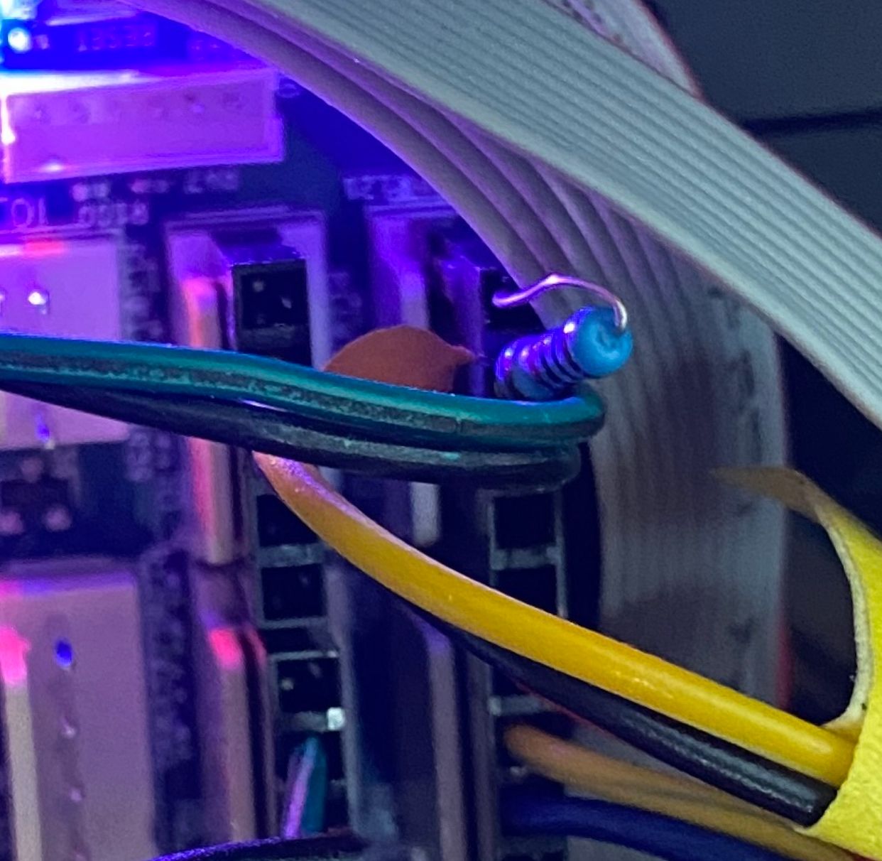
You can crip the resistor right at the Duet board connector like so and slide shrink tube over the wire and resistor:
dont follow the pinout, this is an old photo with the cap.
