Railcore Build Homing In The Incorrect Direction
-
new railcore and im having an issue with the homing direction, when I run an x and y stepper test with
G91
G1 H2 X10 F3000
&
G91
G1 H2 Y10 F3000the head moves to the appropriate direction,
however, when I'm homing, the axis is moving in the incorrect direction.I'm not sure what the correct parameters are to adjust these settings
thinking its the home files .

; Configuration file for My Printer
; Communication and general
M111 S0 ; Debug off
M550 PRailCore ; Machine name and Netbios name (can be anything you like)
;M551 Pmyrap ; Machine password (used for FTP)
;*** If you have more than one Duet on your network, they must all have different MAC addresses, so change the last digits
;M540 P0xBE:0xEF:0xDE:0xAD:0xFE:0xEE ; Uncomment and change if you want to set a MAC address
;*** Wifi Networking
M552 S1 ; Enable WiFi
M555 P2 ; Set output to look like Marlin
M575 P1 B57600 S1 ; Comms parameters for PanelDueG21 ; Work in millimetres
G90 ; Send absolute coordinates...
M83 ; ...but relative extruder moves; Axis and motor configuration
M669 K1 ; CoreXY modeM584 X0 Y1 Z5:6:7 E3:4:8:9 ; Map Z to drivers 5, 6, 7. Define unused drivers 3,4,8 and 9 as extruders
M569 P0 S0 ; Drive 0 goes forwards (change to S0 to reverse it) X stepper (Rear)
M569 P1 S1 ; Drive 1 goes backwards Y Stepper (Front)
M569 P2 S1 ; Drive 2 goes forwards Unused
M569 P3 S0 ; Drive 3 goes forwards Extruder
M569 P4 S1 ; Drive 4 goes forwards Extruder (unused)
M569 P5 S0 ; Drive 5 goes backwards Front Left Z
M569 P6 S0 ; Drive 6 goes backwards Rear Left Z
M569 P7 S0 ; Drive 7 goes backwards Right Z;Leadscrew locations
M671 X-10:-10:333 Y22.5:277.5:150 S7.5 ;Front left, Rear Left, Right S7.5 is the max correction - measure your own offsets, to the bolt for the yoke of each leadscrewM350 X16 Y16 Z16 E16 I1 ; set 16x microstepping for axes& extruder, with interpolation
M574 X1 Y1 Z0 S1 ; set homing switch configuration (x,y at min, z at max) IF YOU NEED TO REVERSE YOUR HOMING SWITCHES CHANGE S1 to S0
M906 X1400 Y1400 Z1000 E800 I60 ; Set motor currents (mA)
M201 X3000 Y3000 Z100 E1500 ; Accelerations (mm/s^2)
M203 X24000 Y24000 Z900 E3600 ; Maximum speeds (mm/min)
M566 X1000 Y1000 Z100 E1500 ; Maximum jerk speeds mm/minute
M208 X290 Y290 Z280 ; set axis maxima and high homing switch positions (adjust to suit your machine)
M208 X0 Y0 Z-0.5 S1 ; set axis minima and low homing switch positions (adjust to make X=0 and Y=0 the edges of the bed)
M92 X200 Y200 Z1600 E837 ; steps/mm; Thermistors
M305 P0 T100000 B3950 R4700 H0 L0 ; Put your own H and/or L values here to set the bed thermistor ADC correction
;If you have a Slice Engineering thermistor, comment out the next line
M305 P1 T100000 B4725 R4700 H0 L0 C7.06e-8 ; Put your own H and/or L values here to set the first nozzle thermistor ADC correction
;If you have a Slice Engineering thermistor, uncomment the next lines. KITS DO NOT SHIP WITH A SLICE THERMISTOR - ONLY UNCOMMENT IF YOU ORDERED ONE
M305 P1 T500000 B4723 C1.196220e-7 ; Set thermistor + ADC parameters for slice thermistorM307 H0 A240.3 C608.7 D8.2 V24.1 B0 ; Bed Heaters
M307 H1 A270.7 C90.4 D6.7 V24.0 B0 ;Heater 1 model
M570 S360 ; Hot end may be a little slow to heat up so allow it 180 seconds
M143 S285; Fans
M106 P0 H-1 ; disable thermostatic mode for fan 0
M106 P1 H-1 ; disable thermostatic mode for fan 1
M106 P2 H-1
M106 P0 S0 ; turn off fans
M106 P1 S0
M106 P2 S0; Tool definitions
M563 P0 D0 H1 ; Define tool 0
G10 P0 S0 R0 ; Set tool 0 operating and standby temperatures
;*** If you have a single-nozzle build, comment the next 2 lines
;M563 P1 D1 H2 ; Define tool 1
;G10 P1 S0 R0 X0 Y17 ; Set tool 1 operating and standby temperatures; Z probe and compensation definition
;*** If you have a switch instead of an IR probe, change P1 to P4 in the following M558 command
; IR PRobe - uncomment the following 2 lines if you have a and IR Probe, and comment out the BLTouch section below
;M558 P4 X0 Y0 Z1 ; Z probe is an IR probe and is not used for homing any axes
;G31 X0 Y30 Z2.00 P500 ; Set the zprobe height and threshold (put your own values here);BLTouch - comment out the following 3 lines if using a IR Probe
M307 H3 A-1 C-1 D-1
M558 P9 X0 Y0 Z1 H5 F50 T6000 A5 S0.02
G31 X-4 Y42 Z2.65 P25 ; Customize your offsets appropriately - do a paper test, and put the probed value in the Z value here;
T0 ; select first hot end -
Well if the axes move in the correct direction when command the problem must be in your homing files.
Please post them using the </> tag.
Frederick
-
@fcwilt sorry I'm not familiar with the </> format
X-axis homing file for dc42 Duet firmware
G91
G1 Z4 F200 H2
G1 X-300 F3000 H1
G1 X4 F600
G1 X-10 H1
G1 Z-4 F200 H2
G90y axis
G91
G1 Z4 F200 H2
G1 Y-320 F3000 H1
G1 Y4 F600
G1 Y-10 H1
G1 Z-4 F200 H2
G90 -
Printers: a small Utilmaker style, a small CoreXY and a E3D MS/TC setup. Various hotends. Using Duet 3 hardware running 3.4.6
-
@fcwilt could you give an example of what the looks like ?
- the x any y files are seperate*
-
@fcwilt
do you mean thisM574 X1 S0
M574 Y1 S0
M574 Z0 S0 -
@tycarr that is not needed for RRF2 so ignore the need to split them out.
your homing file for Y instructs it to go towards the minima of the axis, which is where you indicate the Y endstop is. This indicates its actually one of your motors turning the wrong way.
Can you repost your original image but mark up which direct is + and - for X and Y and where the endstops are?
-
im still pretty new to this and the directions are kind of confusing to know what movement is actually - and + ,
this is the railcore starting moves link , when i run these moves the machine moves into the correct positions
x motor
G91
G1 H2 X10 F3000y motor
G91
G1 H2 Y10 F3000

https://railcore.dozuki.com/Guide/S)+First+Moves/19?lang=en -
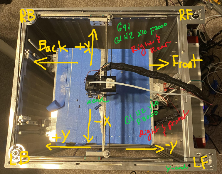
OK, based on the way you're currently set up, I have marked up the image above, to show which way everything is going.
I think the first step is to determine what you want to call the front of the machine. typically, the X axis goes left to right and the y axis goes forwards and backwards. You also need to determine which axis is X and which is Y.Does that make sense?
-
@jay_s_uk yeah i get that part
-
@tycarr so your M671 locations are in the wrong place.
So when jogging your motors, do they move in the directions as indicated in my image above?
-
@tycarr What board are you running on your RailCore? And what firmware?
There is a baseline for the RailCore on the railcore webpage. I can give you my config, but you need to running RRF3.3.0 I am also running a Duet3 Mini 5+ and a 1LC toolboard@jay_s_uk This printer is confusing, took me a while to get my head round it!
Where the markup in the picture is +Y and -Y in yellow, that is actually the X axis
So X0Y0 is bottom left of the picture. Y280 is at the top of the picture.
It is all relevant to the hole in the front panel.P.
-
@paulhew said in Railcore Build Homing In The Incorrect Direction:
Where the markup in the picture is +Y and -Y in yellow, that is actually the X axis
I also thought that might be the case but the OP marked up the X endstop as being on the carriage.
But I definitely agree with you, very confusingOwns various duet boards and is the main wiki maintainer for the Teamgloomy LPC/STM32 port of RRF. Assume I'm running whatever the latest beta/stable build is
-
@Tycarr If you need some help with the RailCore, let me know.
Just incase you did not know, there is a RailCore group on Discord.
If you have a discord username, let me have it and I will invite you, unless you have already found it!P.
-
@jay_s_uk You have to ignore where the hotend fan is pointing, as it points left, looking at the front of the printer.
-
@paulhew I'm not sure what the fan has to do with it
-
@jay_s_uk

Thats the front of the printer.A majority of printers you would see the hotend fan facing you, like the Ender3, Vorons etc.
Thats how I and some people get lost.Side View

P.