Duet3D Logo Duet3D
    • Tags
    • Documentation
    • Order
    • Register
    • Login

    Dual z Stop and Piezo Bed Level

    Scheduled Pinned Locked Moved
    Firmware installation
    5
    24
    889
    Loading More Posts
    • Oldest to Newest
    • Newest to Oldest
    • Most Votes
    Reply
    • Reply as topic
    Log in to reply
    This topic has been deleted. Only users with topic management privileges can see it.
    • ukwebbundefined
      ukwebb @Palgon
      last edited by

      @palgon no one can give you the exact measurements, other than you, as you have the printer to measure it!.

      Home your printer, then move the print head Y position until it's in line with your Y rods. That will give you the Y value.eg something around 165
      Then make sure x is at the 0 position and measure the distance from the tip of the nozzle to the approx centre of the z rod.
      You'll get something like -30mm. Then move the X across as close as you can to the right side, and again measure the nozzle to rod distance. Remembering to add in the X position. So if the head is at position 330, and the rod is a further 30mm away, then your number is 360mm.

      So in the examples above the positions would be -30,165 and 360,165

      1 Reply Last reply Reply Quote 0
      • DIY-O-Sphereundefined
        DIY-O-Sphere @Palgon
        last edited by DIY-O-Sphere

        @palgon said in Dual z Stop and Piezo Bed Level:

        Do you have any tips or a checklist that I should now work through?

        If you have uploaded the complete zip, DWC should be updated.
        If you have access to DWC you can check versions under Setting/General and Machine Specific

        As several commands and files have changed under RRF3 generate a new config under
        https://configtool.reprapfirmware.org

        (UTC+1)

        Palgonundefined 1 Reply Last reply Reply Quote 0
        • Palgonundefined
          Palgon @DIY-O-Sphere
          last edited by

          @diy-o-sphere i have created a new rrf3 config i have saved my old one on my pc and on a usb stick so everything should be up to date then and thanks for your quick reply was just unsure since everything is new territory for me

          fcwiltundefined 1 Reply Last reply Reply Quote 0
          • fcwiltundefined
            fcwilt @Palgon
            last edited by

            @palgon

            Hi,

            Do you have dual Z axis endstop sensors?

            Thanks

            Frederick

            Printers: a small Utilmaker style, a small CoreXY and a E3D MS/TC setup. Various hotends. Using Duet 3 hardware running 3.4.6

            Palgonundefined 1 Reply Last reply Reply Quote 0
            • Palgonundefined
              Palgon @fcwilt
              last edited by

              @fcwilt I use two Z motors on my hevors which are connected on the board at slot Z1(Z2 is plugged with jumpers) and E1 and they both have their own limit switch

              fcwiltundefined 1 Reply Last reply Reply Quote 0
              • fcwiltundefined
                fcwilt @Palgon
                last edited by

                @palgon

                OK with two Z endstop sensors (or limit switches as you called them) ignore anything you read about homing Z with the Z probe.

                You will be homing with the Z endstop sensors.

                The Z probe will be used for:

                • setting the Z=0 datum - which is needed for the next two items
                • leveling the bed using the two Z steppers
                • creating height maps for use with mesh compensation

                Do you know how to configure for that?

                Frederick

                Printers: a small Utilmaker style, a small CoreXY and a E3D MS/TC setup. Various hotends. Using Duet 3 hardware running 3.4.6

                Palgonundefined 1 Reply Last reply Reply Quote 0
                • Palgonundefined
                  Palgon @fcwilt
                  last edited by Palgon

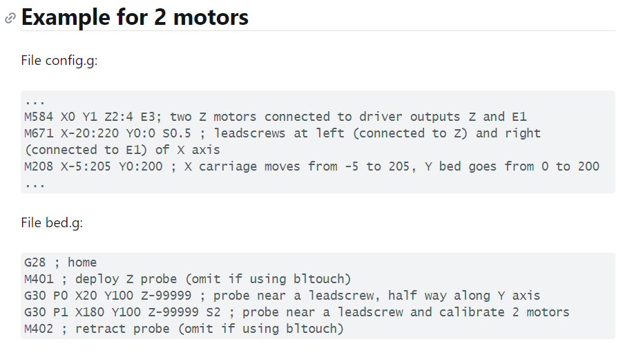
                  @fcwilt i'm trying to read up on this right now but i'm currently at this report https://duet3d.dozuki.com/Wiki/Bed_levelling_using_multiple_independent_Z_motors and looking at what i have to do in the bed.g in the config.g i currently only have M584 X0 Y1 Z2:4 E3 and
                  M671 X-25:165 Y355:165 S20 inserted further I am not yet
                  and i need to somehow integrate the endstop sensors (e1) well my goal is that it stops each axis individually and the piezo then applies the mash

                  1 Reply Last reply Reply Quote 0
                  • DIY-O-Sphereundefined
                    DIY-O-Sphere
                    last edited by

                    @palgon

                    https://duet3d.dozuki.com/Wiki/Gcode#Section_M574_RepRapFirmware_Num_3
                    Find the example for two Z-motors

                    (UTC+1)

                    1 Reply Last reply Reply Quote 0
                    • Palgonundefined
                      Palgon
                      last edited by

                      how is that actually must one under rrf3 also everywhere where a z axis is defined a u axis add or searches the somewhere out for example with m350 /m92 /m201or m208 and can it be that I have the M584 command wrong because in my old M584 XO Y1 Z2:3 U3 E4 is written

                      DIY-O-Sphereundefined fcwiltundefined 2 Replies Last reply Reply Quote 0
                      • DIY-O-Sphereundefined
                        DIY-O-Sphere @Palgon
                        last edited by DIY-O-Sphere

                        @palgon
                        Extruder is swaped with 2. motor of Z

                        Edit:
                        M584 X0 Y1 Z2:4 E3
                        should be
                        M584 X0 Y1 Z2:3 E4

                        (UTC+1)

                        Palgonundefined 1 Reply Last reply Reply Quote 0
                        • Palgonundefined
                          Palgon @DIY-O-Sphere
                          last edited by Palgon

                          @diy-o-sphere have a clean cfg on the printer where nothing is difiniert. this I have now copied times and test times edited and this is now the result
                          config.g

                          can the following command actually be inserted under M584 or where must it be inserted M574 Z1 S1 P "io2.in+io3.in" ; Z axis with two motors, individual min endstops, active high

                          DIY-O-Sphereundefined 1 Reply Last reply Reply Quote 0
                          • fcwiltundefined
                            fcwilt @Palgon
                            last edited by

                            @palgon said in Dual z Stop and Piezo Bed Level:

                            how is that actually must one under rrf3 also everywhere where a z axis is defined a u axis add or searches the somewhere out for example with m350 /m92 /m201or m208 and can it be that I have the M584 command wrong because in my old M584 XO Y1 Z2:3 U3 E4 is written

                            Under older versions of the firmware you had to breakout one of the Z steppers as another letter.

                            Now you don't have to do that because the M574 command for the Z axis allows specifying two endstop sensors.

                            My printer controlled by a Duet 2 WiFI/Diuex 5 combo has three Z steppers and this is what the M574 command looks like for the Z axis:

                            M574 Z1 S1 P"!duex.e2stop + !duex.e3stop + !duex.e4stop" ; configure active-high endstop for low  end on Z
                            

                            Frederick

                            Printers: a small Utilmaker style, a small CoreXY and a E3D MS/TC setup. Various hotends. Using Duet 3 hardware running 3.4.6

                            1 Reply Last reply Reply Quote 0
                            • DIY-O-Sphereundefined
                              DIY-O-Sphere @Palgon
                              last edited by DIY-O-Sphere

                              @palgon said in Dual z Stop and Piezo Bed Level:

                              config.g

                              Below should be the correct code for limits and endstops but there are to much other issues
                              like
                              M671 missing
                              Wrong declaration of Z-Probe
                              So I also expect issus with the generated files for homing beg.g ...etc.
                              To much to fix by hand....

                              Got through the configurator step by step

                              ; Axis Limits
                              M208 X0 Y0 Z0 S1                                   ; set axis minima
                              M208 X295 Y295 Z390 S0                             ; set axis maxima
                              
                              ; Endstops
                              M574 X1 S1 P"xstop"                                ; configure active-high endstop for low end on X via pin xstop
                              M574 Y1 S1 P"ystop"                                ; configure active-high endstop for low end on Y via pin ystop
                              M574 Z1 S1 P"zstop+e0stop"                         ; configure active-high endstop for low end on Z via pin zstop+e0stop
                              

                              (UTC+1)

                              Palgonundefined 1 Reply Last reply Reply Quote 0
                              • Palgonundefined
                                Palgon @DIY-O-Sphere
                                last edited by

                                @diy-o-sphere I'm just a newbie when it comes to writing cfg and am today (25 Jul 2021, 17:49) just started with rrf3 and to the z prob entries I have not yet come because it's all very new to me I need longer for. because I have to read everything but thanks for the right end stops and because the printer under 2.05.1 is also only run without sample I wanted to work out the first time again and then teach him how he has to move with the sensor 🙂

                                DIY-O-Sphereundefined 1 Reply Last reply Reply Quote 0
                                • DIY-O-Sphereundefined
                                  DIY-O-Sphere @Palgon
                                  last edited by

                                  @palgon

                                  If you want to do it step by step, that's fine, I just wondered.
                                  I have also done the conversion to RRF3 by hand and really learned a lot.
                                  But I would still recommend to do as much as possible with the tool, even if you only take it as a reverence to compare...

                                  (UTC+1)

                                  Palgonundefined 1 Reply Last reply Reply Quote 0
                                  • Palgonundefined
                                    Palgon @DIY-O-Sphere
                                    last edited by

                                    @diy-o-sphere I'm just about to create another one with the tool this time even with piezo settings am curious how the same looks 🙂

                                    Palgonundefined 1 Reply Last reply Reply Quote 0
                                    • Palgonundefined
                                      Palgon @Palgon
                                      last edited by

                                      @DIY-O-Sphere the newly created cfg looks totally different hope that this looks better and that I'm not on the wrong track. and yes I have to insert m671 and then also that in the bed.g . furthermore I have to look at what the manufacturer makes for information on M558

                                      the whole thing I will do tomorrow

                                      19178e75-dcde-496a-8fa1-4ace505bf3bd-image.png

                                      fcwiltundefined 1 Reply Last reply Reply Quote 0
                                      • fcwiltundefined
                                        fcwilt @Palgon
                                        last edited by

                                        @palgon

                                        While the configurator tool and many folks put the M671 command in config.g I put it it bed.g because it is related to the operation of bed.g and nothing else.

                                        It also means if I need to change M671 I edit bed.g and the next time I do G32 the new M671 settings take effect - no need to re-boot the printer to cause config.g to be processed again.

                                        It is just my personal preference and it doesn't change the behavior of bed leveling.

                                        Also remember to set the Z=0 datum (with a single G30) after leveling the bed.

                                        Frederick

                                        Printers: a small Utilmaker style, a small CoreXY and a E3D MS/TC setup. Various hotends. Using Duet 3 hardware running 3.4.6

                                        1 Reply Last reply Reply Quote 1
                                        • First post
                                          Last post
                                        Unless otherwise noted, all forum content is licensed under CC-BY-SA