• Tags
  • Documentation
  • Order
  • Register
  • Login
Duet3D Logo Duet3D
  • Tags
  • Documentation
  • Order
  • Register
  • Login

#- (hash) printer with super simple gantry

Scheduled Pinned Locked Moved
Example setups and prints
anti-racking dual roller constraint hash printer
11
65
6.4k
Loading More Posts
  • Oldest to Newest
  • Newest to Oldest
  • Most Votes
Reply
  • Reply as topic
Log in to reply
This topic has been deleted. Only users with topic management privileges can see it.
  • undefined
    o_lampe
    last edited by o_lampe 22 Jul 2021, 16:07

    Hi gents,
    I started pondering the idea to build a hash-printer with the least amount of hardware. The video of the original design shows the typical shaft & dual belt approach we've seen on H-bots and cross-gantry printers to avoid racking.
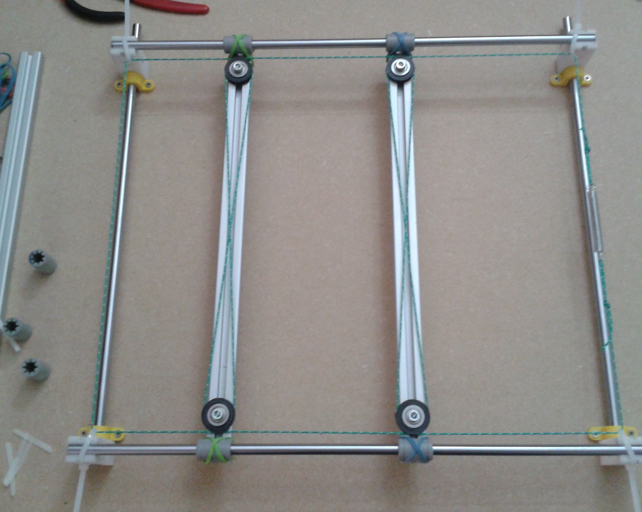
    But I want to use a dual roller constraint as I did on other occasions before. I wasn't sure if that would also work with two beams per axis, so I cobbled together a quick and dirty test rig.
    2021-07-22 17.55.37.jpg

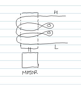
    To make it clearer how to wrap the Aramid fishing line around the four rollers I started with a drawing:
    dual_dual-constraint.jpg

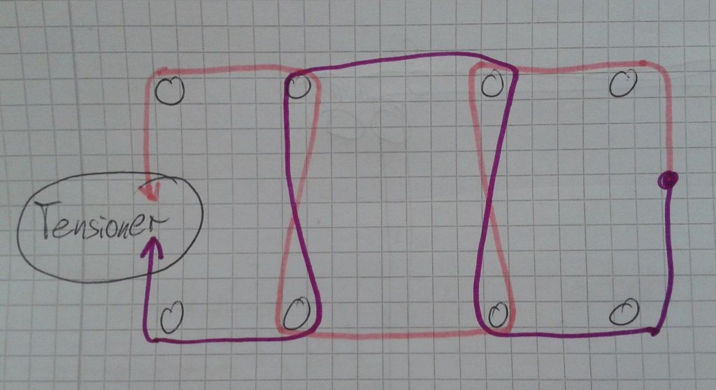
    This is the Y-axis only, imagine two more extrusions horizontally to build a '#'.

    And finally I made demo video to show how easy it is to move the beam from only one side without racking.

    1 Reply Last reply Reply Quote 3
    • undefined
      o_lampe
      last edited by 29 Jul 2021, 17:22

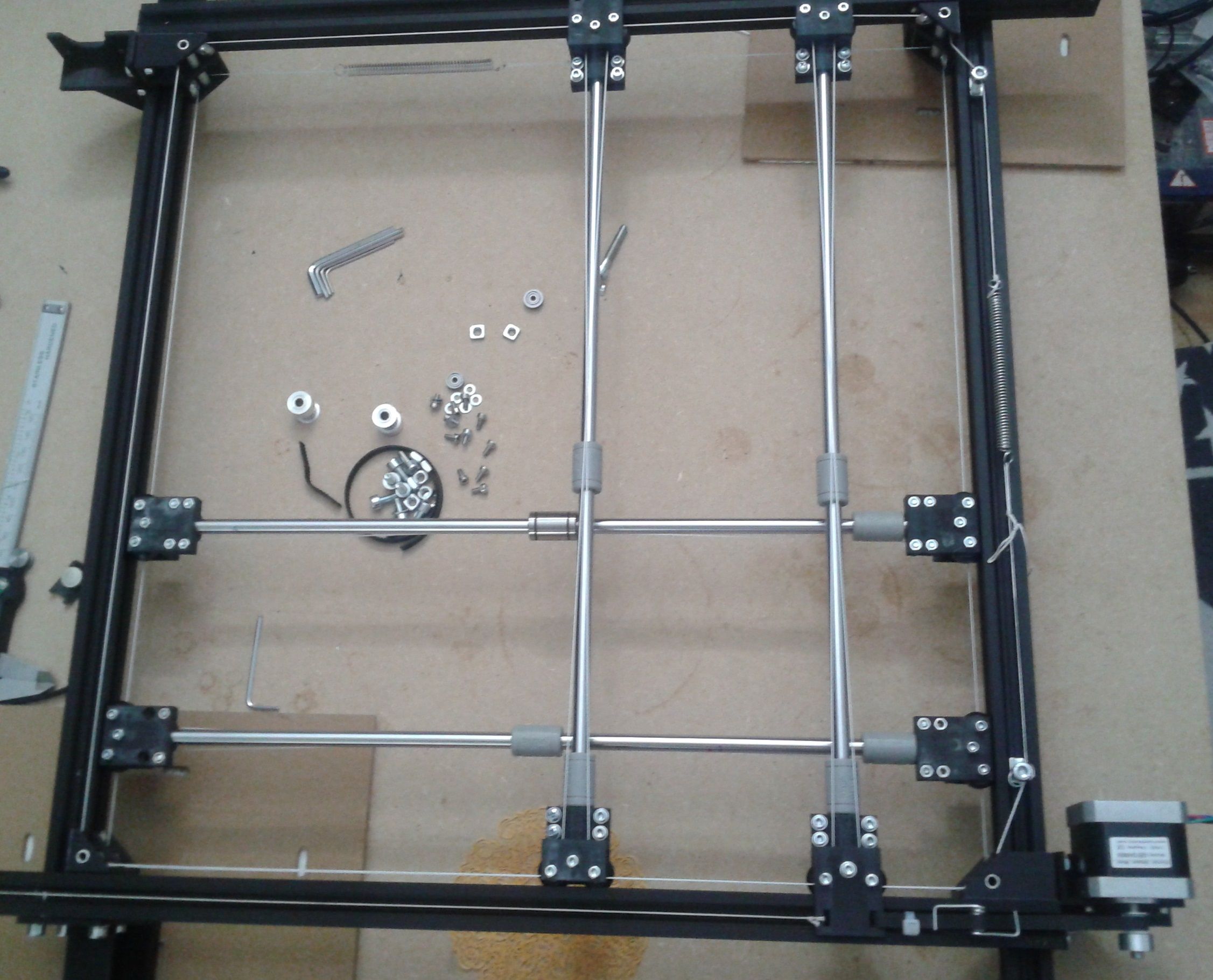
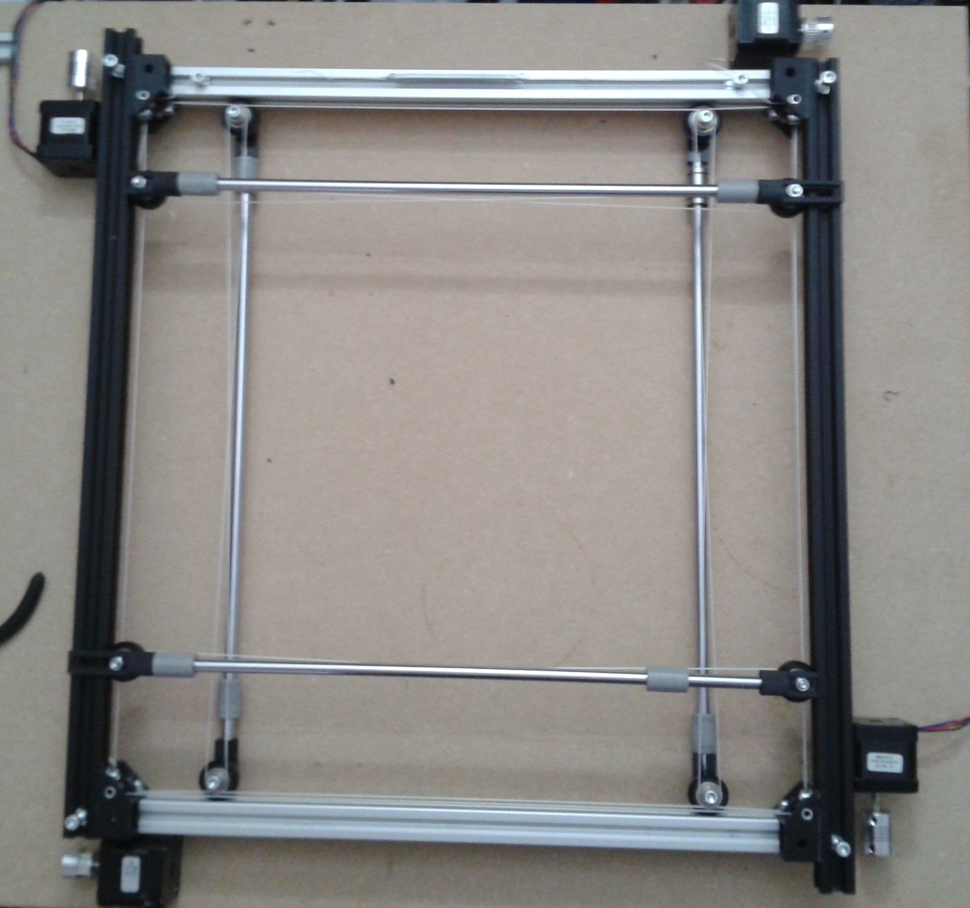
      Stage two of the printer insanity.
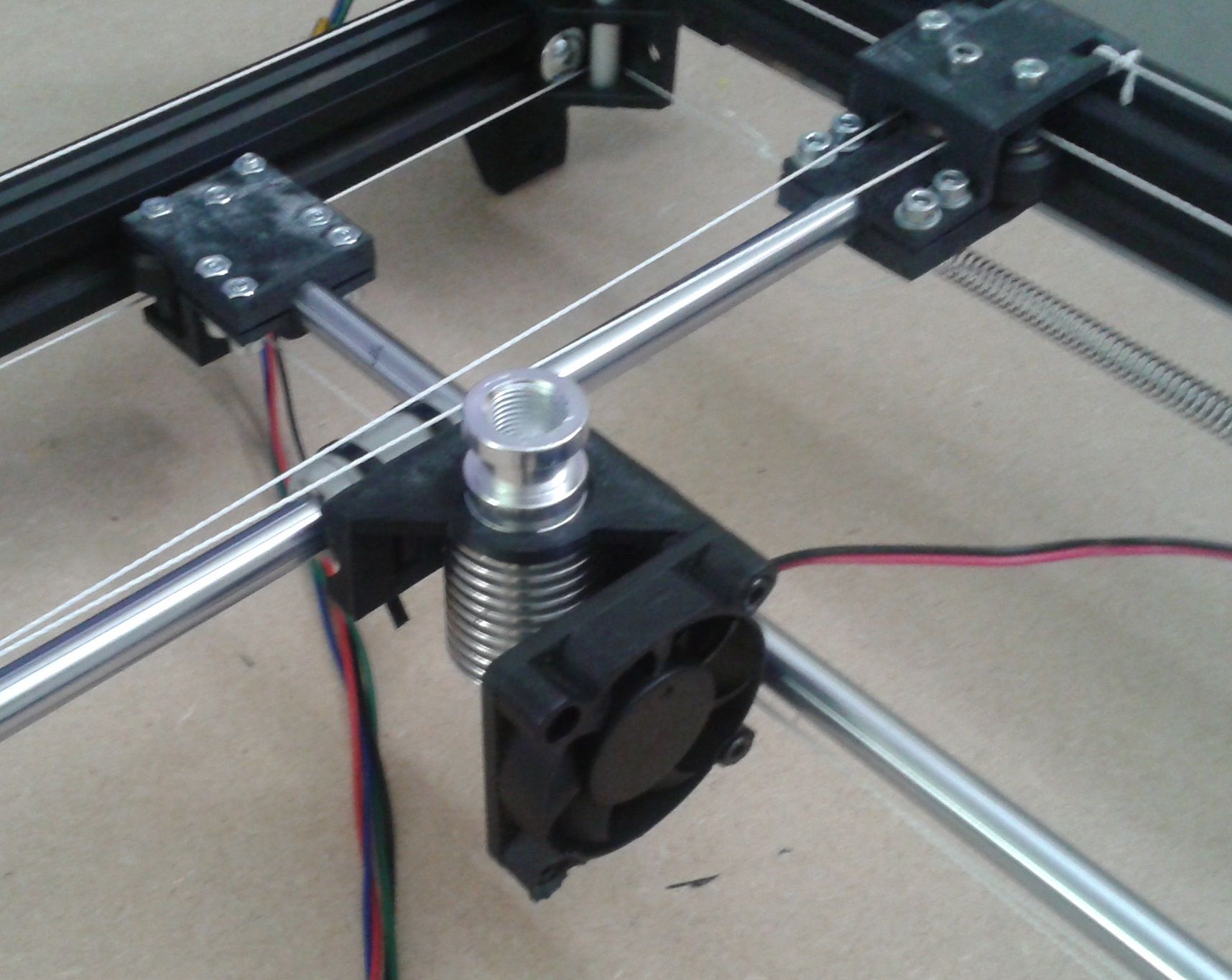
      I made corner brackets with aluminum guides for the aramid line and some rod-connectors with V-wheel and dual roller.
      Wrapping the lines around the dual rollers is very tricky, especially because I was so bold to use only one roller per side.
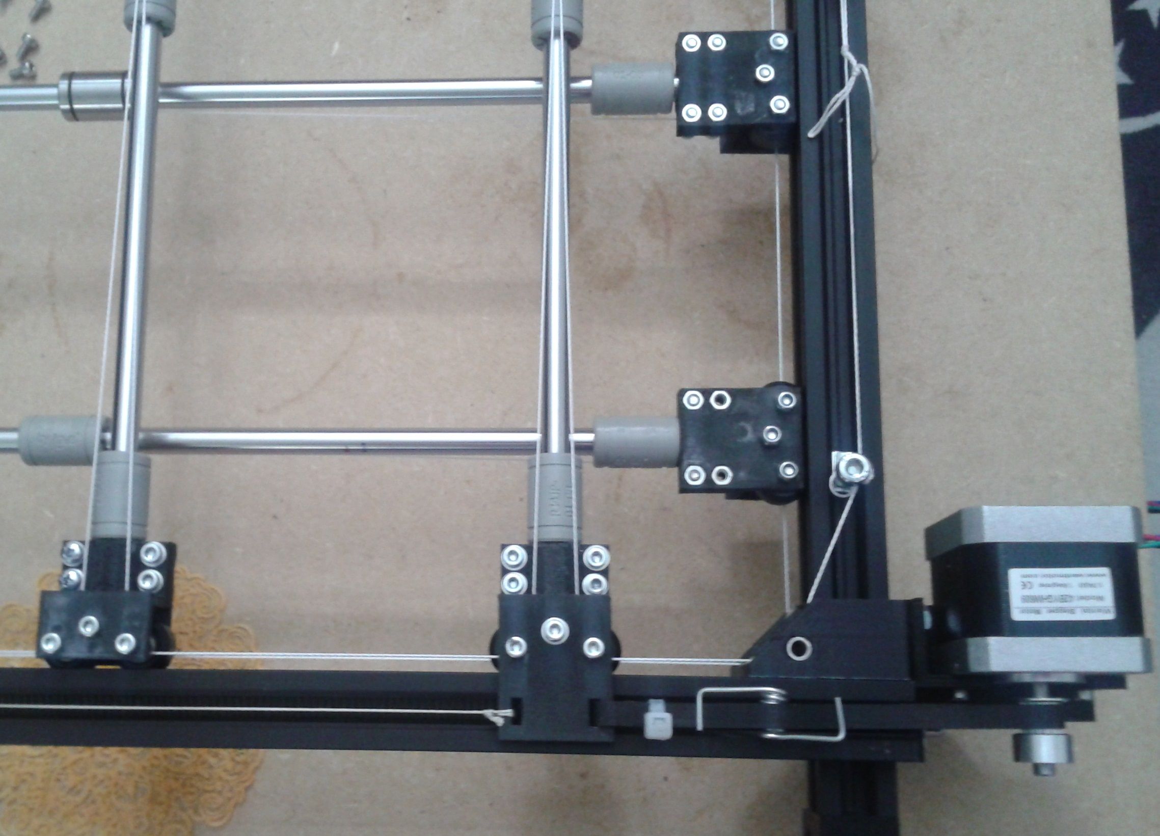
      But once they are tightened, they run smooth without racking. The rods need a toolholder that connects both linear bearings, which is next on the list. Otherwise they tend to tilt because of the single v-wheel thing...

      Overview with 4 steppers in roughly the right orientation.
      2021-07-29 19.03.19.jpg

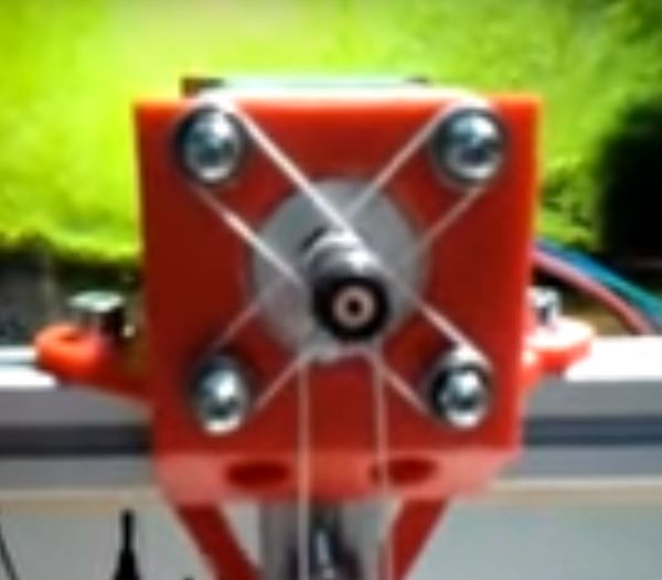
      Closeup of a corner with aramid line.
      2021-07-29 18.45.16.jpg

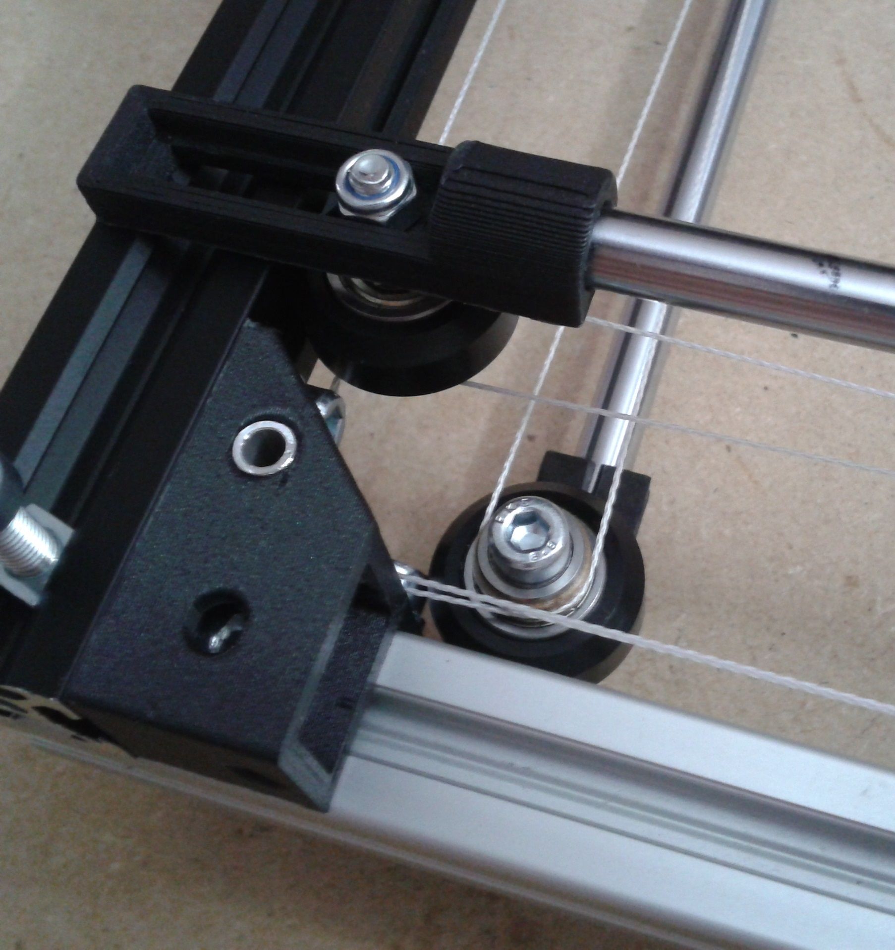
      The brownish thing is the dual roller.
      2021-07-29 17.04.21.jpg

      1 Reply Last reply Reply Quote 0
      • undefined
        o_lampe
        last edited by 30 Jul 2021, 05:51

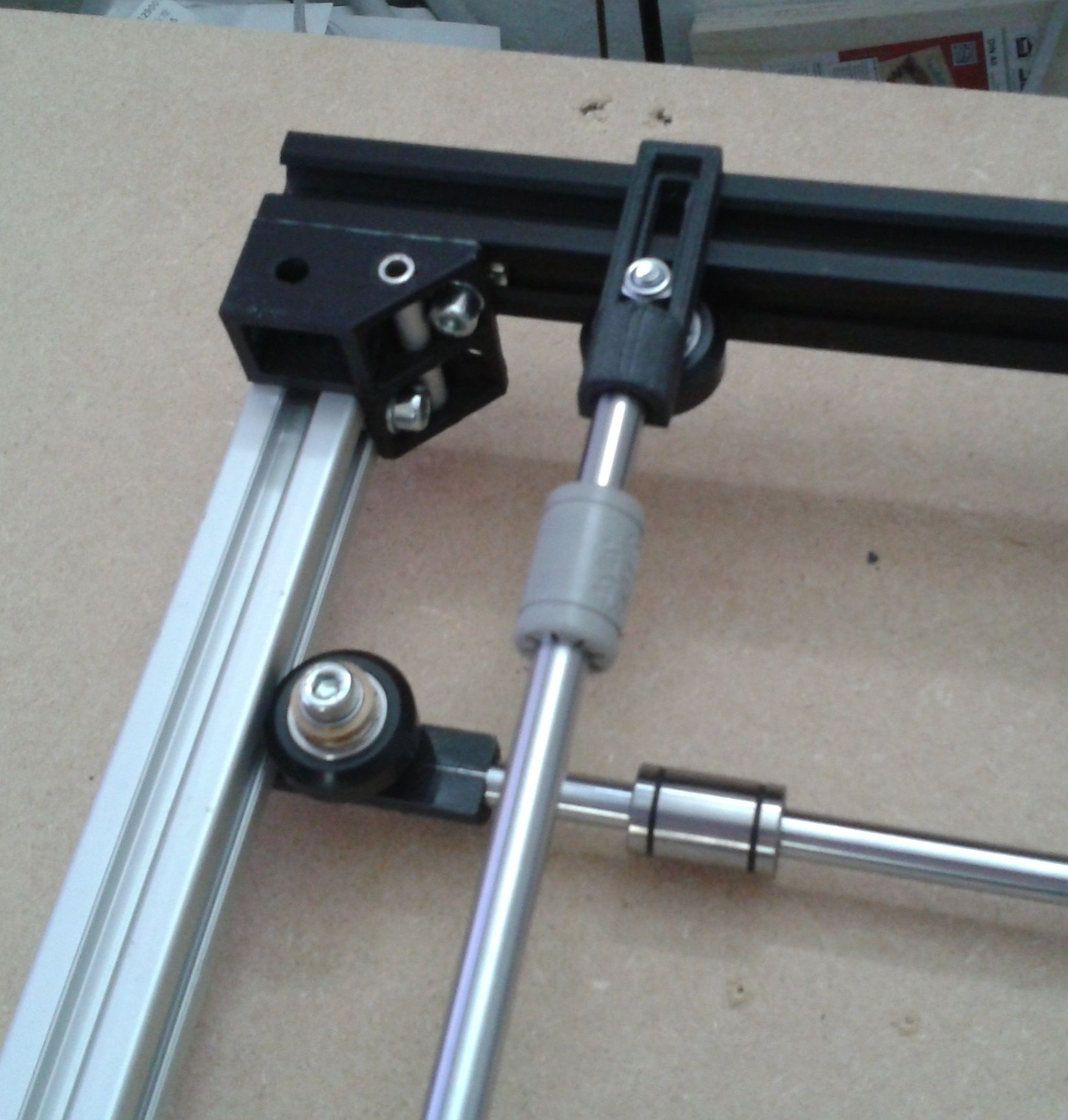
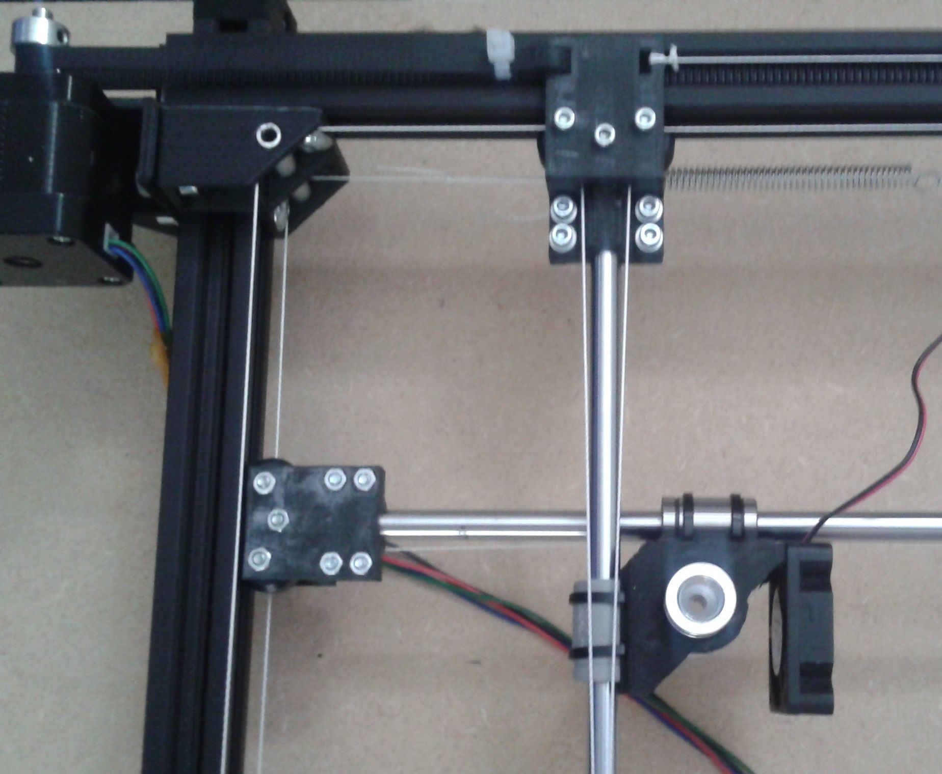
        Overnight the aramid line tension showed another weakness in the rod-connector. They look bend.
        I have to support the rollers from both sides, which makes it even harder to wrap the line around...
        Back to the drawing board 🙂

        1 Reply Last reply Reply Quote 0
        • undefined
          kingofthegeeks
          last edited by 30 Jul 2021, 19:25

          I really like what your doing here, I'm intending to design one of these as well.

          This has helped me start visualizing my own intentions, thank you for that.

          Mike

          undefined 1 Reply Last reply 31 Jul 2021, 06:21 Reply Quote 0
          • undefined
            o_lampe @kingofthegeeks
            last edited by o_lampe 31 Jul 2021, 06:21

            @kingofthegeeks
            Thanks for the reply. competition is always a good thing. I hope you share your design too.
            If money wouldn't matter, I'd build it with linear rails instead of smooth rods. But I have to use what's laying around (salvaged my old Prusa I3)
            My main intention is to demonstrate the functionality of the dual roller constrain vs extended motor shaft & dual belts of the original design.
            It saves me 8 extended shafts and tons of idler rollers.

            undefined 1 Reply Last reply 31 Jul 2021, 06:32 Reply Quote 0
            • undefined
              fcwilt @o_lampe
              last edited by 31 Jul 2021, 06:32

              @o_lampe said in #- (hash) printer with super simple gantry:

              My main intention is to demonstrate the functionality of the dual roller constrain vs extended motor shaft & dual belts of the original design.
              It saves me 8 extended shafts and tons of idler rollers.

              Do you have a picture of this "original design" with the parts you are trying to not use?

              Thanks.

              Frederick

              Printers: a small Utilmaker style, a small CoreXY and a E3D MS/TC setup. Various hotends. Using Duet 3 hardware running 3.4.6

              undefined 1 Reply Last reply 31 Jul 2021, 06:44 Reply Quote 0
              • undefined
                o_lampe @fcwilt
                last edited by o_lampe 31 Jul 2021, 06:44

                @fcwilt
                No, you'd have to watch the video in slowMotion.
                TBH, I'm not sure if there are 8 shaft-extenders in total, but it's definitely a complex setup.

                //edit after watching it again, I'm sure you could get away with 4 extended shafts, when you put the idler bearings next to the drive pulleys of the other axis (or on their own shaft)

                undefined 1 Reply Last reply 31 Jul 2021, 13:22 Reply Quote 0
                • undefined
                  fcwilt @o_lampe
                  last edited by 31 Jul 2021, 13:22

                  @o_lampe

                  Thanks for the link - I see what you mean.

                  Interesting but way too complicated to my way of thinking. It would be a pain to get the nozzles exactly in the same plane.

                  My approach to a cross-gantry system (just a single tool) uses two steppers per X and Y axis. That would not lend itself to the multi-tool approach as seen in the video.

                  Good luck and keep us up to date.

                  Frederick

                  Printers: a small Utilmaker style, a small CoreXY and a E3D MS/TC setup. Various hotends. Using Duet 3 hardware running 3.4.6

                  undefined 1 Reply Last reply 31 Jul 2021, 14:07 Reply Quote 0
                  • undefined
                    o_lampe @fcwilt
                    last edited by 31 Jul 2021, 14:07

                    @fcwilt said in #- (hash) printer with super simple gantry:

                    It would be a pain to get the nozzles exactly in the same plane.

                    My idea is to have all idle tooholders parking outside of the bed and adjust nozzle height in the toolchanging macros.
                    With multi-stream gcode coming up, I hope the Duet team will also introduce multi z motors (mini z-axis on the tool to adjust z for each nozzle individually)
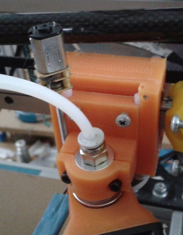
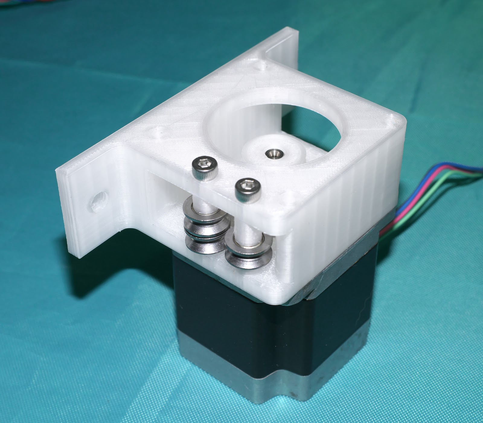
                    I'd go for a N20 motor with M3 leadscrew on my sliding E3D clamp.

                    Mockup N20 on e3d slider :
                    e3d-slider_n20_front.jpg

                    1 Reply Last reply Reply Quote 1
                    • undefined
                      o_lampe
                      last edited by o_lampe 31 Jul 2021, 14:29

                      @o_lampe said in #- (hash) printer with super simple gantry:

                      With multi-stream gcode coming up, I hope the Duet team will also introduce multi z motors (mini z-axis on the tool to adjust z for each nozzle individually)

                      @dc42 and duet team
                      I just had an idea how to split z-axis adjustment (mesh levelling) from regular z- moves (layer change) for the soon_to_come mini Z-axis:

                      A gcode line that doesn't have a Z-move applies mesh levelling to the mini-Z motor
                      A gcode line with z-move applies the motion to the regular Z-motor(s)

                      1 Reply Last reply Reply Quote 0
                      • undefined
                        o_lampe
                        last edited by o_lampe 14 Aug 2021, 06:24

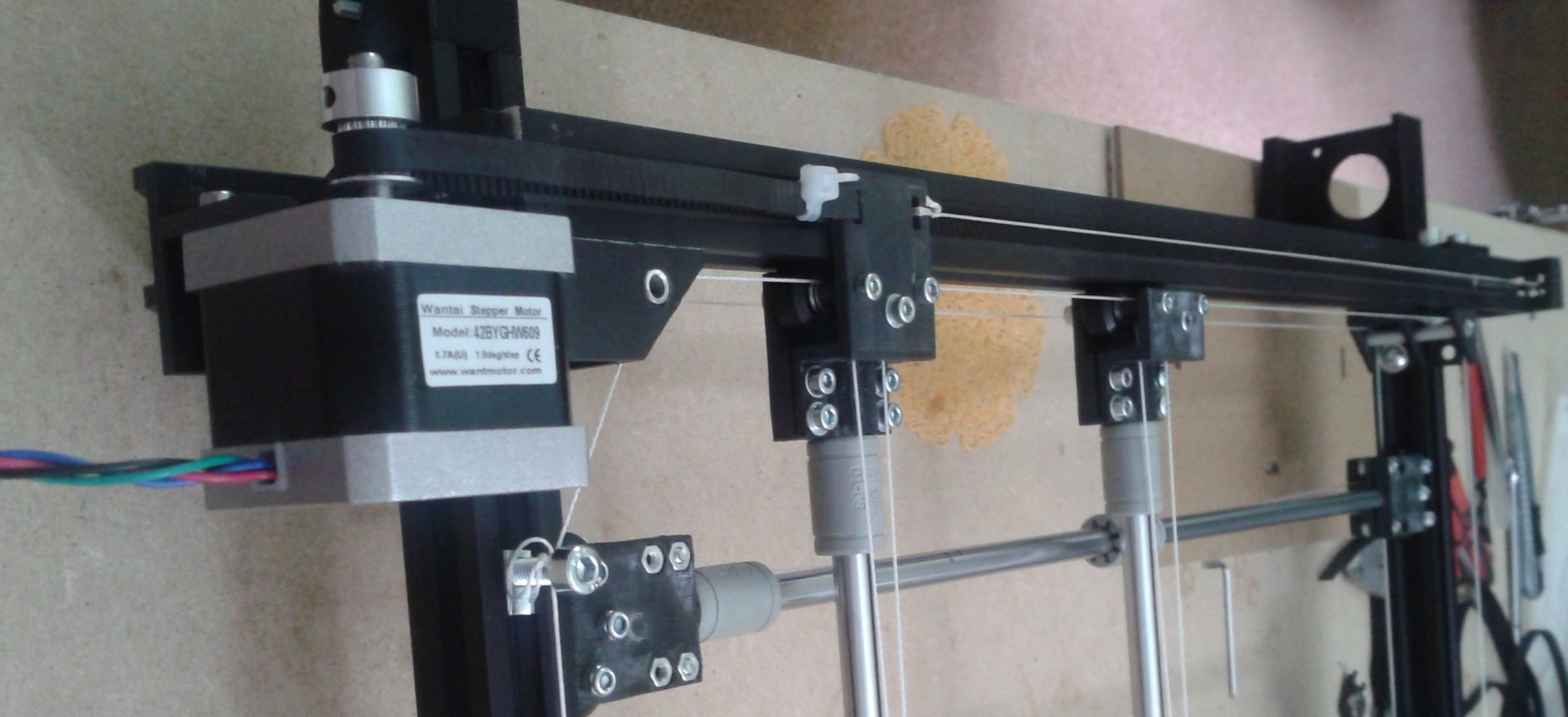
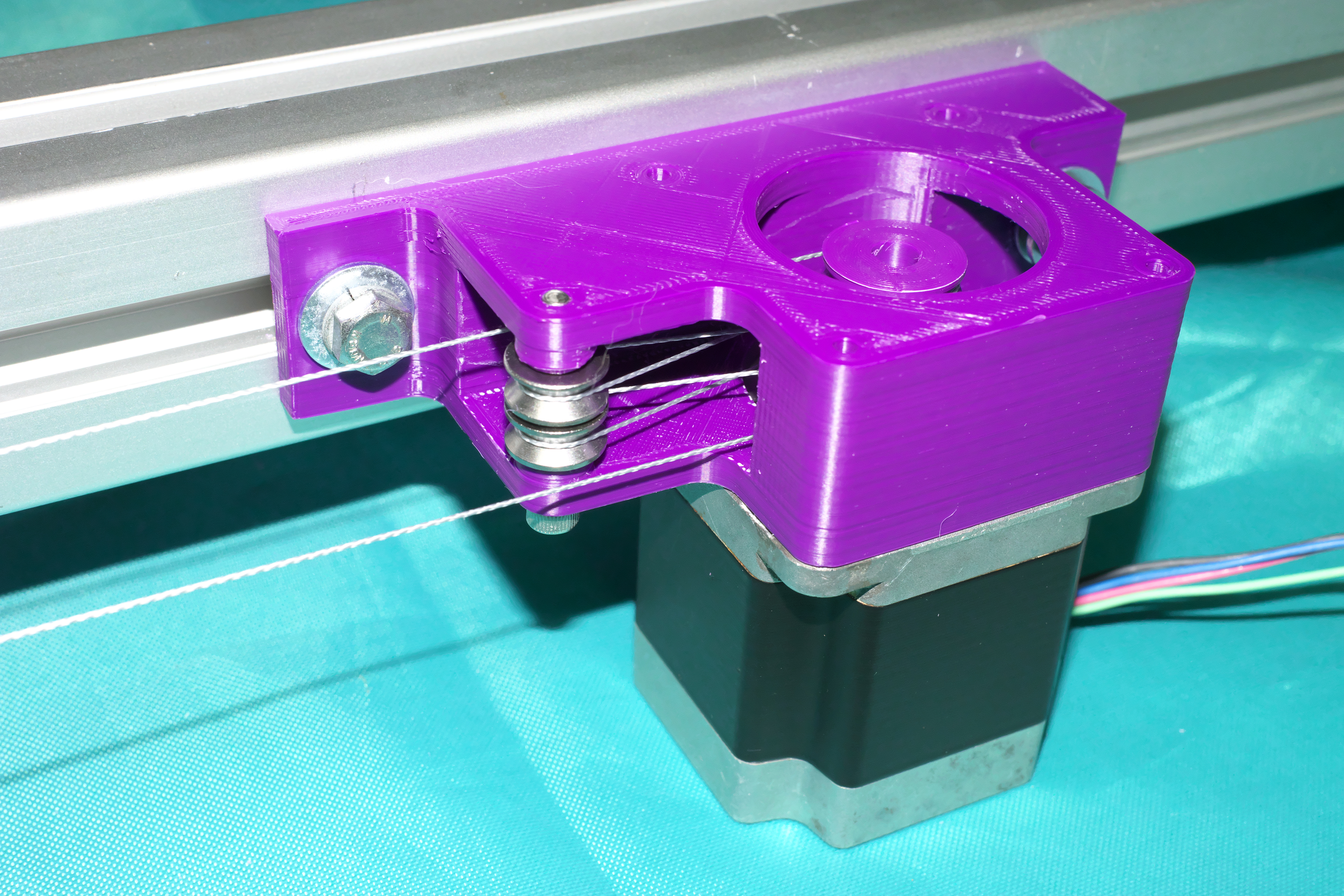
                        I designed a new carrier, now with two small V-wheels and the dual roller in between. It's also closer to the smooth rod and supported from both sides (always practice what you preach)
                        I think it will not bend under tension as before.

                        2021-08-13 15.46.21.jpg

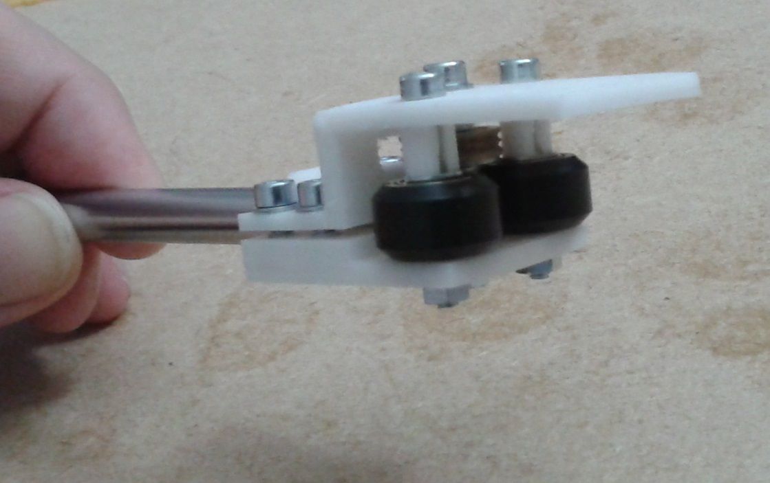
                        Printer is still busy spitting out all the carriers, I decided to use 0.2 nozzle against 0.8 for finer details.

                        1 Reply Last reply Reply Quote 1
                        • undefined
                          o_lampe
                          last edited by o_lampe 21 Aug 2021, 11:30

                          1st. sign of life today 😁
                          I've finished printing parts, assembled the top frame and installed the first stepper. Did some slowmo and superfast (500mm/s) moves without seeing any issues.
                          2021-08-21 13.13.36.jpg
                          2021-08-21 13.13.43.jpg

                          Even the belt has got some 'aramid'
                          2021-08-21 13.18.26.jpg

                          I will only have two endstops for all the axes, they are IR beam brakers and home to the center of the bed.

                          Next step: install all steppers and make some basic toolholders.

                          mrehorstdmdundefined 1 Reply Last reply 21 Aug 2021, 12:41 Reply Quote 0
                          • mrehorstdmdundefined
                            mrehorstdmd @o_lampe
                            last edited by mrehorstdmd 21 Aug 2021, 12:41

                            @o_lampe How are you handling the cable at the motors? I tried a corexy mechanism with cable drive and eventually gave up on it as too difficult to maintain. Part of the problem was getting sufficient tension in the cable to have adequate friction with the drive pulleys. You can't just let the cable wind on top of itself as that will get noisy and lead to imprecision in the mechanism. In order to get precision and quiet operation you have to ensure that the cable doesn't wind on top of itself or walk across the drive pulley as the motor turns. I used motor mounts like this:

                            undefined

                            undefined

                            undefined

                            The steering pulleys prevent the cable from overlapping on the motor pulley and provide a consistent location for the cable that doesn't change with position of the carriage.

                            The crappy little pulleys I used clattered loudly in operation, but the biggest problem I ran into was maintenance. Once you let tension off the cable so you can take things apart or make adjustments, the cable comes off all the pulleys. It's quite difficult to get it back onto all the pulleys at once without a second or even third set of hands to move the cable around.

                            I also found that cable stretches quite a bit, especially compared to a belt- that may be a problem for achieving precise motion.

                            https://drmrehorst.blogspot.com/

                            undefined 1 Reply Last reply 21 Aug 2021, 13:42 Reply Quote 0
                            • undefined
                              o_lampe @mrehorstdmd
                              last edited by 21 Aug 2021, 13:42

                              @mrehorstdmd
                              I remember we had the same discussion a few years back, which resulted in my 'cloverleaf drive" tests.
                              cloverleaf.jpg

                              But this time I only replaced the unused belt-part with aramid line. Truth be told, I had a few pieces of GT2 belt, but they were too short, so...

                              mrehorstdmdundefined 1 Reply Last reply 21 Aug 2021, 14:56 Reply Quote 0
                              • mrehorstdmdundefined
                                mrehorstdmd @o_lampe
                                last edited by 21 Aug 2021, 14:56

                                @o_lampe oh yeah, I remember now. Never mind...

                                https://drmrehorst.blogspot.com/

                                1 Reply Last reply Reply Quote 0
                                • undefined
                                  o_lampe
                                  last edited by 23 Aug 2021, 12:55

                                  First Toolholder for an E3D heatsink. I can add a sherpa mini or bowden extruder.
                                  2021-08-23 14.49.50.jpg 2021-08-23 14.49.56.jpg

                                  1 Reply Last reply Reply Quote 0
                                  • undefined
                                    o_lampe
                                    last edited by o_lampe 27 Aug 2021, 08:33

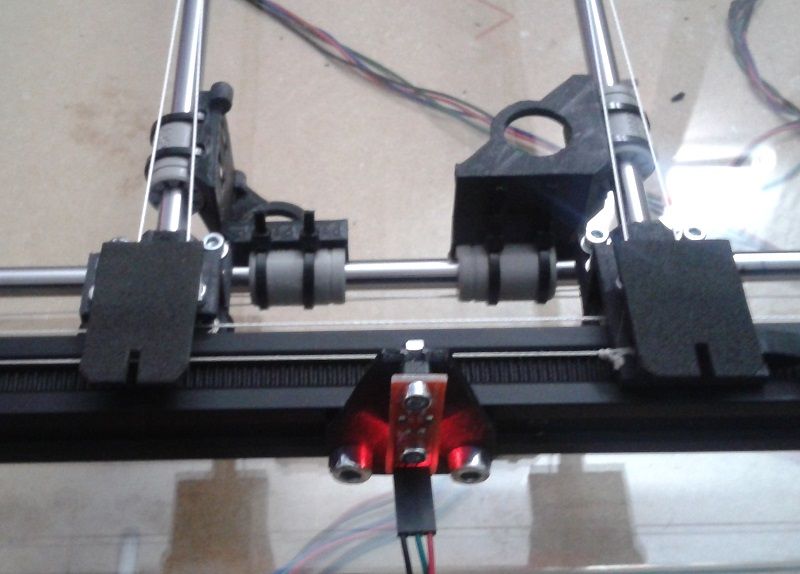
                                    I've installed two beam braker endstops and wrote homing files.
                                    They work fine, when called independently, but using homeall throws an error. "Failed to enable endstops"
                                    Here's a homing file (check out, how I define/invert and delete the endstop)

                                    ; homeU.g
                                    M574 U2 S1 P"Xmax"   ; change endstop
                                    M400
                                    G91              ; relative positioning
                                    ;G1 H2 Z5 F6000   ; lift Z relative to current position
                                    G1 H1 U295 F6000 ; move quickly to X axis endstop and stop there (first pass)
                                    M574 U2 S1 P"!Xmax"   ; change endstop
                                    M400
                                    G1 H1 U29 F360  ; move slowly to x axis endstop once more (second pass)
                                    G92 U0
                                    
                                    ;G1 H2 Z-5 F6000  ; lower Z again
                                    G90              ; absolute positioning
                                    M574 U2 S1 P"Nil"   ; delete endstop
                                    M400
                                    G1 U-130 F24000


                                    Homeall just calles all macros one by one, so where's my mistake?

                                    ; homeall.g
                                    ; called to home all axes
                                    ;
                                    m98 p"homeX.g"
                                    m98 p"homeY.g"
                                    m98 p"homeU.g"
                                    m98 p"homeV.g"
                                    ;G1 Z5 F100           ; lift Z relative to current position
                                    G90                  ; absolute positioning
                                    

                                    RRF3.3.0_6 on a F407ZG controller

                                    Here's a pic of the endstop with the extra cutout
                                    hash-endstop.jpg

                                    cosmowaveundefined 1 Reply Last reply 27 Aug 2021, 08:54 Reply Quote 0
                                    • cosmowaveundefined
                                      cosmowave @o_lampe
                                      last edited by 27 Aug 2021, 08:54

                                      @o_lampe what's in your other home macros? Can you please post them?

                                      Mankati FSXT+, DeltaTowerV2, E3D MS/TC

                                      undefined 1 Reply Last reply 27 Aug 2021, 11:44 Reply Quote 0
                                      • undefined
                                        o_lampe @cosmowave
                                        last edited by 27 Aug 2021, 11:44

                                        @cosmowave they're almost the same, except the specific parking positions and neg/pos signs of the homing moves.

                                        ; homeV.g
                                        M574 V2 S1 P"ymax"   ; define endstop
                                        M400
                                        G91              ; relative positioning
                                        ;G1 H2 Z5 F6000   ; lift Z relative to current position
                                        G1 H1 V-295 F6000 ; move quickly to Y axis endstop and stop there (first pass)
                                        M574 V2 S1 P"!ymax"   ; invert endstop
                                        M400
                                        G1 H1 V-29 F360  ; move slowly to Y axis endstop once more (second pass)
                                        G92 V0
                                        
                                        ;G1 H2 Z-5 F6000  ; lower Z again
                                        G90              ; absolute positioning
                                        M574 V2 S1 P"nil"   ; delete endstop
                                        M400
                                        G1 V170 F24000
                                        
                                        ; homeX.g
                                        M574 X2 S1 P"Xmax"   ; change endstop
                                        M400
                                        G91              ; relative positioning
                                        ;G1 H2 Z5 F6000   ; lift Z relative to current position
                                        G1 H1 X295 F6000 ; move quickly to x axis endstop and stop there (first pass)
                                        M574 X2 S1 P"!Xmax"   ; change endstop
                                        M400
                                        G1 H1 X29 F360  ; move slowly to x axis endstop once more (second pass)
                                        G92 X0
                                        
                                        ;G1 H2 Z-5 F6000  ; lower Z again
                                        G90              ; absolute positioning
                                        M574 X2 S1 P"Nil"   ; delete endstop
                                        M400
                                        G1 X-185 F24000
                                        
                                        ; homey.g
                                        M574 Y2 S1 P"ymax"   ; change endstop
                                        M400
                                        G91              ; relative positioning
                                        ;G1 H2 Z5 F6000   ; lift Z relative to current position
                                        G1 H1 Y295 F6000 ; move quickly to Y axis endstop and stop there (first pass)
                                        M574 Y2 S1 P"!ymax"   ; change endstop
                                        M400
                                        G1 H1 Y29 F360  ; move slowly to Y axis endstop once more (second pass)
                                        G92 Y0
                                        
                                        ;G1 H2 Z-5 F6000  ; lower Z again
                                        G90              ; absolute positioning
                                        M574 Y2 S1 P"Nil"   ; delete endstop
                                        M400
                                        G1 Y-174 F24000
                                        
                                        
                                        cosmowaveundefined 1 Reply Last reply 27 Aug 2021, 11:53 Reply Quote 0
                                        • cosmowaveundefined
                                          cosmowave @o_lampe
                                          last edited by 27 Aug 2021, 11:53

                                          @o_lampe I'm not sure if the command M400 after setting/deleting the endstop will work correctly!? Perhaps it helps to change it to a short delay with G4?

                                          Mankati FSXT+, DeltaTowerV2, E3D MS/TC

                                          undefined 1 Reply Last reply 27 Aug 2021, 12:17 Reply Quote 0
                                          • First post
                                            Last post
                                          Unless otherwise noted, all forum content is licensed under CC-BY-SA