Bad PT100 board?
-
I have a DuetWifi V1.0 board. Everything was running fine last week. When I turn it on today, it does not sense my extruder temperature. If I try to turn on my heaters, it generates a very loud pitched noise.
The first thing I suspect was a bad connection. I measured the resistance at the RTD1 terminals with the machine off and it was around 120 ohms. I checked all the connections and it seems fine.
Unfortunately, while working, the terminal on the board broke off. Since RTD2 was not used, I moved the wires to those terminals and changed my M308 to use "spi.cs2". I was not able to read any temperature on the RTD2 port either.
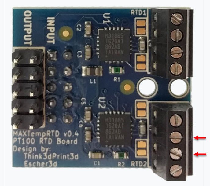
Just as a sanity check, I unplugged the wires and put in a 100 ohm resistor in the terminals shown with red arrows. I can't read 0 degrees on my PanelDue or web interface. There is no temperature display for the extruder.
I'm just wondering if the board went bad or if its a bad setting. Its hard to say its a bad setting when everything was working fine last week.
Does anyone have suggestions? I haven't probed the PT100 board yet or hooked it up to a logic analyzer. It just seems like its an upward battle since I migrated to RRF3.
; Configuration file for Duet WiFi
; executed by the firmware on start-up

; ---------------------------- General Settings ------------------------------------
M111 S0 		; Debugging off
G21 			; Work in millimeters
G90 			; Send absolute coordinates...
M83 			; ...but relative extruder moves
M555 P1 		; Set firmware compatibility to look like RepRapFirmare

; ---------------------------- Printer Bed Settings ------------------------------------
; Rod length settings for reference:
; L = Ideal Length / Measured_length * Original Delta Rod Length
; Larger Number = Smaller part size
; Smaller Number = Larger part size

; Delta Radius setting for reference:
; Lower number  - Middle get looser
; Higher number - Middle get tighter

; MANUAL CALIBRATION DATA
M665 L438.000 R264 H424.75 B150 				; M665 - Set delta radius, diagonal rod length, printable radius and homed height, B = safe printing radius
M666 X0 Y0 Z0									; M666 - Put your endstop adjustments here, or let auto calibration find them

; ---------------------------- Motor and Extruder Settings ------------------------------------
; Motor Settings
M569 P0 S1 										; Drive 0 (S0 = Backwards; S1 = Forwards)  X-Axis
M569 P1 S1 										; Drive 1 (S0 = Backwards; S1 = Forwards)  Y-Axis
M569 P2 S1 										; Drive 2 (S0 = Backwards; S1 = Forwards)  Z-Axis
M569 P3 S0 										; Drive 3 (S0 = Backwards; S1 = Forwards)  Extruder
M350 X16 X16 X16 X16 I1 						; Configure microstepping without interpolation
M906 X1000 Y1000 Z1000 E600 I30 				; Set motor currents (mA) and motor idle factor in per cent
M84 S30 										; Set motor idle timeout

; Acceleration, Jerk and speed
M566 X1000 Y1000 Z900 E170 						; Jerk - Set maximum instantaneous speed changes (mm/min)
M201 X2000 Y2000 Z2000 E200 					; Set accelerations (mm/s^2)
M203 X20000 Y20000 Z20000 E5000 				; Set maximum speeds (mm/min)

; Extruder
M92 X80 Y80 Z80 E2680 							; Set steps per mm; E value is in mm/minute    E2715
M572 D0 S0.18  									; Extruder pressure advance

; ---------------------------- End Stops ------------------------------------
; Endstops
M574 X2 S1 P"xstop" 							; Configure active-high endstop for high end on X via pin xstop
M574 Y2 S1 P"ystop" 							; Configure active-high endstop for high end on Y via pin ystop
M574 Z2 S1 P"zstop" 							; Configure active-high endstop for high end on Z via pin zstop


; ---------------------------- Bed Level and Probe Settings ------------------------------------
; Grid Mesh
M557 X5:205 Y5:165 S20 								; Define mesh grid

;Precision Piezo Settings
M558 P1 C"zprobe.in" H1 F400 T10000 R0.5 S0.1 A6  	; R- Recoverty Time before probing start; A - max times to probe each point; S - tolerance with each probe
G31 P500 X0 Y0 Z0.08 								; Set Z probe trigger value, offset and trigger height  (increasing z makes nozzle go lower)


; ---------------------------- Motor and Extruder Settings ------------------------------------
;Bed Heater
M308 S0 P"bed_temp" Y"thermistor" T100000 B3950 R4700 L0 H9		; Define bed temperature sensor
M950 H0 C"bed_heat" T0 											; Heater 0 uses the bed_heat pin, sensor 0
M307 H0 A366.5 C667.4 D11.7 S1.00 V0.0 B1 						; Bed heater setting
M140 H0															; Map heated bed to heater 0
M143 S100 														; Set maximum heater temperature to 100C
M570 S200 														; Set maximum heating time to 200s

;Extruder Heater
;M308 S1 P"spi.cs1" Y"rtd-max31865" F60	A"RTD1"					; Define E0 temperature sensor, RTD1
M308 S1 P"spi.cs2" Y"rtd-max31865" F60 A"RTD2"	    			; Define E0 temperature sensor, RTD2
M950 H1 C"e0heat" T1 											; Heater 1 uses the e0heat pin and sensor 1
M307 H1 A347.2 C180.2 D4.8 S1.00 V12.0 B0 						; Hot End heater setting

; ---------------------------- Fan Settings ------------------------------------
; Fan mapping
M950 F0 C"fan0" Q500		; Map Fan 0 to P0
M950 F1 C"fan1" Q500		; Map Fan 1 to P1
M950 F2 C"fan2" Q500		; Map Fan 2 to P2

; Fan Settings
M106 P0 B0 S0 H-1 			; Set fan 0 value, Thermostatic control is turned off
M106 P1 B0 S0 H-1 			; Set fan 1 value, Thermostatic control is turned off
M106 P2 B0 S0 H-1 			; Set fan 2 value, Thermostatic control is turned off

; ---------------------------- Tool Settings ------------------------------------
M563 P0 D0 H1 				; Define tool 0
G10 P0 X0 Y0 Z0 			; Set tool 0 axis offsets
G10 P0 R175 S190			; Set initial tool 0 active and standby temperatures.  R= standby S= active

; ---------------------------- Network Settings ------------------------------------
M552 S1 					; Enable network and acquire dynamic address via DHCP
M575 S1 P1 B57600			; Set the Serial Communication parameters
Board: Duet 2 WiFi (2WiFi)
Firmware: RepRapFirmware for Duet 2 WiFi/Ethernet 3.3 (2021-06-15)
Duet WiFi Server Version: 1.26 -
@shadowx said in Bad PT100 board?:
M350 X16 X16 X16 X16 I1
I don't know if this is intentional, but you're setting the microstepping for the X axis 4 times in a row here but not the other axis.
As for your PT100 problems, have you tried reseating the board in it's connector yet?
Can you measure the resistance of R1 and R2 resistors? They should read ~400 ohms.
@shadowx said in Bad PT100 board?:
Just as a sanity check, I unplugged the wires and put in a 100 ohm resistor in the terminals shown with red arrows. I can't read 0 degrees on my PanelDue or web interface. There is no temperature display for the extruder.
What exactly does it display for a temperature?
Finally, can you send M98 P"config.g" just to check for any syntax errors in your config?
-
@shadowx with that board revision, when using a 2-wire connection or testing with the resistor, you need to add a link wire between terminals 1 and 2 and another between 3 and 4 (with the resistor fitted between terminals 2 and 3 as you have indicated), or alternatively put solder bridges across the pads provided.
Duet WiFi hardware designer and firmware engineer
Please do not ask me for Duet support via PM or email, use the forum
http://www.escher3d.com, https://miscsolutions.wordpress.com -
@phaedrux said in Bad PT100 board?:
@shadowx said in Bad PT100 board?:
M350 X16 X16 X16 X16 I1
I don't know if this is intentional, but you're setting the microstepping for the X axis 4 times in a row here but not the other axis.
That is an error on my part. The error has been there since 2018 and earlier that I overlooked. I have fixed the setting as shown in the results on the bottom of this reply.As for your PT100 problems, have you tried reseating the board in it's connector yet?
I reseated the board multiple times. I took the board in and out at least 5 times.Can you measure the resistance of R1 and R2 resistors? They should read ~400 ohms.
They are both about 400.1-400.5 ohms@shadowx said in Bad PT100 board?:
Just as a sanity check, I unplugged the wires and put in a 100 ohm resistor in the terminals shown with red arrows. I can't read 0 degrees on my PanelDue or web interface. There is no temperature display for the extruder.
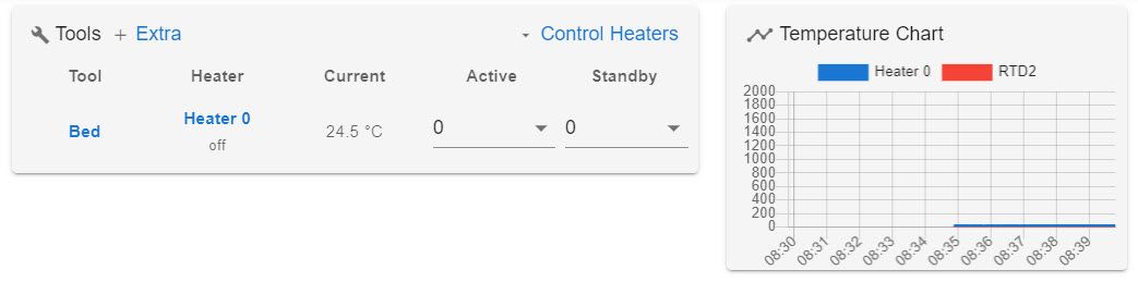
What exactly does it display for a temperature? The PanelDue screen does not show temperature for the extrude and the web interface shows the bottom image.
Finally, can you send M98 P"config.g" just to check for any syntax errors in your config?
Here are the error messages that came back. This is after fixing the M350 command to:
M350 X16 Y16 Z16 E16 I1M98 P"config.g" Error: in file macro line 31 column 19: M350: array too long, max length = 0 Error: in file macro line 32 column 25: M906: array too long, max length = 0 Error: in file macro line 36 column 24: M566: array too long, max length = 0 Error: in file macro line 37 column 25: M201: array too long, max length = 0 Error: in file macro line 38 column 28: M203: array too long, max length = 0 Error: in file macro line 41 column 18: M92: array too long, max length = 0 Error: Invalid extruder number '0' Error: bad drive number Error: Tool 0 not found Error: Tool 0 not foundAt first, after fixing the M350 command, the whining noise was gone and the PanelDue shows "Tool 0 not found". The macro turns on the bed heater bed, but I get the "tool 0 not found" error message. I thought fixing the M350 solved the noise issue at the time.
However, if I shut off the printer and restart it, the noise is back if I run the heater macro right away. After I home the printer, the noise is gone when I start my heater. I guess that noise is related to the motors and homing the printer first before I turn on the heater stopped that noise from happening. Note, when the motors where whining, I did not get a tool error on the panelDue, however, I had to use the stop button or that noise would not stop. After the printer homed, I had no more noise and that tool error message popped right up.
G10 P0 R0 S190  ; Set standby and extruder temp to 200C
M140 S65 H0 	; Set heated bed initial value to 65C
T0 				;  Select Tool 0 to turn on the extruder to active
Thanks for all your help.
-
@dc42 said in Bad PT100 board?:
@shadowx with that board revision, when using a 2-wire connection or testing with the resistor, you need to add a link wire between terminals 1 and 2 and another between 3 and 4 (with the resistor fitted between terminals 2 and 3 as you have indicated), or alternatively put solder bridges across the pads provided.
I use a 4 wire system on my printer. My measurement between the two middle terminal (2 &3) is around 120 ohms. Between connection 1&2, I get around 1.1 ohms and 3&4, I get 1.2 ohms.
On the 100 ohm resistor test, I attached a short jumper cable between 1&2 and 3&4 and still had the same results. The jumper wires measured around 0.7 or 0.8 ohms. Note, these measurements are on the top screws of the terminals on the PWB boards. I wasn't able to probe the bottom solder pads unless I remove the boards.
I just hope it wasn't something stupid I did on the configuration file like left out a semi colon somewhere or added an extra space. I don't believe I changed anything, but its been a least a week since my last print.
I compared it to my last backup in June and I don't see any differences in the extruder heater or tool settings.
-
@shadowx said in Bad PT100 board?:
On the 100 ohm resistor test, I attached a short jumper cable between 1&2 and 3&4 and still had the same results. The jumper wires measured around 0.7 or 0.8 ohms. Note, these measurements are on the top screws of the terminals on the PWB boards. I wasn't able to probe the bottom solder pads unless I remove the boards.
Those measurements sound good. Does the second channel on the PT100 board behave in the same way when you test using the 100 ohm resistor?
Duet WiFi hardware designer and firmware engineer
Please do not ask me for Duet support via PM or email, use the forum
http://www.escher3d.com, https://miscsolutions.wordpress.com -
@dc42 said in Bad PT100 board?:
@shadowx said in Bad PT100 board?:
On the 100 ohm resistor test, I attached a short jumper cable between 1&2 and 3&4 and still had the same results. The jumper wires measured around 0.7 or 0.8 ohms. Note, these measurements are on the top screws of the terminals on the PWB boards. I wasn't able to probe the bottom solder pads unless I remove the boards.
Those measurements sound good. Does the second channel on the PT100 board behave in the same way when you test using the 100 ohm resistor?
Yes. I was only able to test the second channel since the terminals on the RTD1 broke off. I can solder the wires or a connector to the RTD1 solder pads to test.
I have a Kingst LA1010 logic analyzer. Is there certain pins I can connect to on the board to check if I get the proper signals from the RTD board? I recall there was a schematic available somewhere but don't have the links to them anymore. I guess the basic checks is for power first to the board and then any output signals from the SPI interface.
Thanks for you help.
-
There are some issues with your config.g perhaps from the manual transition to RRF3. Here's a clean basic config.g I created in the config tool you can use to start with and modify with your specifics. I tried to copy over as much as I could.
I think part of the problem for those errors is that you lack an M584 command to define the drivers and axis. The whining noise may be due to incorrect defaults being applied for the drivers.
; Configuration file for Duet WiFi (firmware version 3) ; executed by the firmware on start-up ; ; generated by RepRapFirmware Configuration Tool v3.3.0 on Fri Aug 06 2021 12:30:20 GMT-0600 (Central Standard Time) ; General preferences M575 P1 S1 B57600 ; enable support for PanelDue G90 ; send absolute coordinates... M83 ; ...but relative extruder moves M550 P"My Printer" ; set printer name M665 R105.6 L215 B85 H250 ; Set delta radius, diagonal rod length, printable radius and homed height M666 X0 Y0 Z0 ; put your endstop adjustments here, or let auto calibration find them ; Network M552 S1 ; enable network M586 P0 S1 ; enable HTTP M586 P1 S0 ; disable FTP M586 P2 S0 ; disable Telnet ; Drives M569 P0 S1 ; physical drive 0 goes forwards M569 P1 S1 ; physical drive 1 goes forwards M569 P2 S1 ; physical drive 2 goes forwards M569 P3 S0 ; physical drive 3 goes backwards M584 X0 Y1 Z2 E3 ; set drive mapping M350 X16 Y16 Z16 E16 I1 ; configure microstepping with interpolation M92 X80.00 Y80.00 Z80.00 E2680.00 ; set steps per mm M566 X900.00 Y900.00 Z900.00 E1200.00 ; set maximum instantaneous speed changes (mm/min) M203 X18000.00 Y18000.00 Z18000.00 E3000.00 ; set maximum speeds (mm/min) M201 X2000.00 Y2000.00 Z2000.00 E3000.00 ; set accelerations (mm/s^2) M906 X1000 Y1000 Z1000 E800 I30 ; set motor currents (mA) and motor idle factor in per cent M84 S30 ; Set idle timeout ; Axis Limits M208 Z0 S1 ; set minimum Z ; Endstops M574 X2 S1 P"xstop" ; configure active-high endstop for high end on X via pin xstop M574 Y2 S1 P"ystop" ; configure active-high endstop for high end on Y via pin ystop M574 Z2 S1 P"zstop" ; configure active-high endstop for high end on Z via pin zstop ; Z-Probe M558 P1 C"zprobe.in" H5 F480 T6000 ; set Z probe type to unmodulated and the dive height + speeds G31 P500 X0 Y0 Z0.08 ; set Z probe trigger value, offset and trigger height M557 R85 S20 ; define mesh grid ; Heaters M308 S0 P"bedtemp" Y"thermistor" T100000 B3950 ; configure sensor 0 as thermistor on pin bedtemp M950 H0 C"bedheat" T0 ; create bed heater output on bedheat and map it to sensor 0 M307 H0 B0 S1.00 ; disable bang-bang mode for the bed heater and set PWM limit M140 H0 ; map heated bed to heater 0 M143 H0 S120 ; set temperature limit for heater 0 to 120C M308 S1 P"spi.cs2" Y"rtd-max31865" ; configure sensor 1 as thermocouple via CS pin spi.cs2 M950 H1 C"e0heat" T1 ; create nozzle heater output on e0heat and map it to sensor 1 M307 H1 B0 S1.00 ; disable bang-bang mode for heater and set PWM limit M143 H1 S280 ; set temperature limit for heater 1 to 280C ; Fans M950 F0 C"fan0" Q500 ; create fan 0 on pin fan0 and set its frequency M106 P0 S0 H-1 ; set fan 0 value. Thermostatic control is turned off M950 F1 C"fan1" Q500 ; create fan 1 on pin fan1 and set its frequency M106 P1 S0 H-1 ; set fan 1 value. Thermostatic control is turned off M950 F2 C"fan2" Q500 ; create fan 2 on pin fan2 and set its frequency M106 P2 S0 H-1 ; set fan 2 value. Thermostatic control is turned off ; Tools M563 P0 D0 H1 F0 ; define tool 0 G10 P0 X0 Y0 Z0 ; set tool 0 axis offsets G10 P0 R0 S0 ; set initial tool 0 active and standby temperatures to 0C ; Custom settings are not defined ; Miscellaneous M501 ; load saved parameters from non-volatile memory T0 ; select first tool -
@shadowx said in Bad PT100 board?:
@dc42 said in Bad PT100 board?:
@shadowx said in Bad PT100 board?:
On the 100 ohm resistor test, I attached a short jumper cable between 1&2 and 3&4 and still had the same results. The jumper wires measured around 0.7 or 0.8 ohms. Note, these measurements are on the top screws of the terminals on the PWB boards. I wasn't able to probe the bottom solder pads unless I remove the boards.
Those measurements sound good. Does the second channel on the PT100 board behave in the same way when you test using the 100 ohm resistor?
Yes. I was only able to test the second channel since the terminals on the RTD1 broke off. I can solder the wires or a connector to the RTD1 solder pads to test.
I have a Kingst LA1010 logic analyzer. Is there certain pins I can connect to on the board to check if I get the proper signals from the RTD board? I recall there was a schematic available somewhere but don't have the links to them anymore. I guess the basic checks is for power first to the board and then any output signals from the SPI interface.
Thanks for you help.
If you send command M308 S# (where #s the sensor number) with no additional parameters, what is the response? I am assuming you are running RRF 3.
How did the terminals of RTD1 break off? If that was caused by physical damage, perhaps you should just buy another daughter board? They are not expensive, and judging by the version in the photo you attached I suspect you have had that one for several years.
Duet WiFi hardware designer and firmware engineer
Please do not ask me for Duet support via PM or email, use the forum
http://www.escher3d.com, https://miscsolutions.wordpress.com -
@dc42 I think the photo he has in his first post is just the photo used from the wiki page for the PT100 board, not his own board, so not indicative of the version he has.
https://duet3d.dozuki.com/Wiki/Connecting_PT100_temperature_sensors
-
@phaedrux thanks, I didn't consider that.