@phaedrux said in Bad PT100 board?:
@shadowx said in Bad PT100 board?:
M350 X16 X16 X16 X16 I1
I don't know if this is intentional, but you're setting the microstepping for the X axis 4 times in a row here but not the other axis.
That is an error on my part. The error has been there since 2018 and earlier that I overlooked. I have fixed the setting as shown in the results on the bottom of this reply.
As for your PT100 problems, have you tried reseating the board in it's connector yet?
I reseated the board multiple times. I took the board in and out at least 5 times.
Can you measure the resistance of R1 and R2 resistors? They should read ~400 ohms.
They are both about 400.1-400.5 ohms
@shadowx said in Bad PT100 board?:
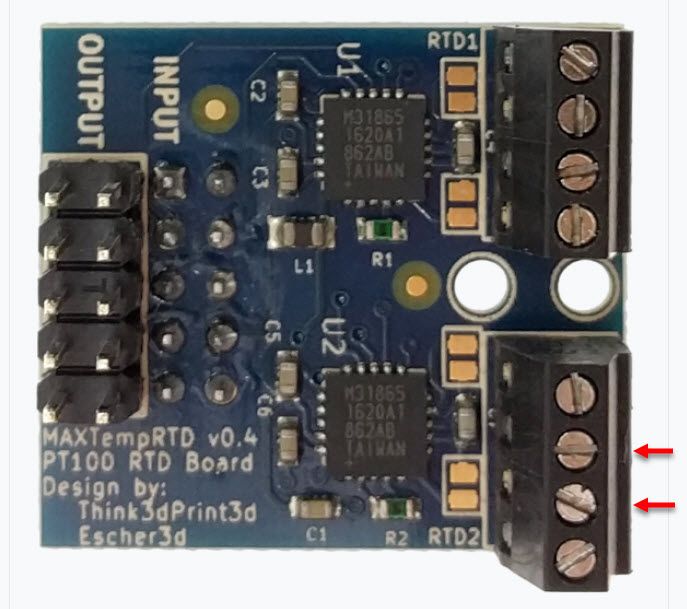
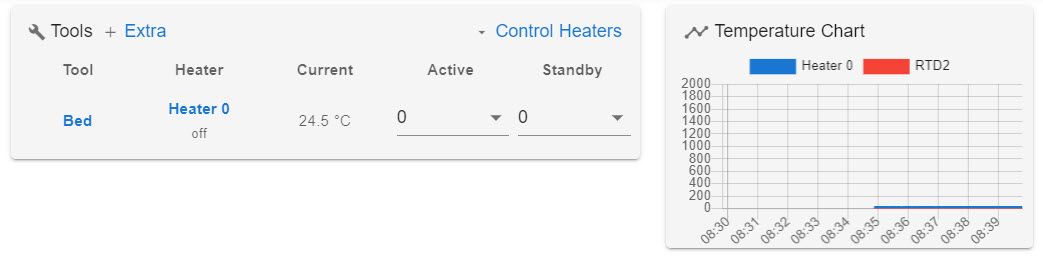
Just as a sanity check, I unplugged the wires and put in a 100 ohm resistor in the terminals shown with red arrows. I can't read 0 degrees on my PanelDue or web interface. There is no temperature display for the extruder.
What exactly does it display for a temperature? The PanelDue screen does not show temperature for the extrude and the web interface shows the bottom image.
Finally, can you send M98 P"config.g" just to check for any syntax errors in your config?
Here are the error messages that came back. This is after fixing the M350 command to:
M350 X16 Y16 Z16 E16 I1
M98 P"config.g"
Error: in file macro line 31 column 19: M350: array too long, max length = 0
Error: in file macro line 32 column 25: M906: array too long, max length = 0
Error: in file macro line 36 column 24: M566: array too long, max length = 0
Error: in file macro line 37 column 25: M201: array too long, max length = 0
Error: in file macro line 38 column 28: M203: array too long, max length = 0
Error: in file macro line 41 column 18: M92: array too long, max length = 0
Error: Invalid extruder number '0'
Error: bad drive number
Error: Tool 0 not found
Error: Tool 0 not found
At first, after fixing the M350 command, the whining noise was gone and the PanelDue shows "Tool 0 not found". The macro turns on the bed heater bed, but I get the "tool 0 not found" error message. I thought fixing the M350 solved the noise issue at the time.
However, if I shut off the printer and restart it, the noise is back if I run the heater macro right away. After I home the printer, the noise is gone when I start my heater. I guess that noise is related to the motors and homing the printer first before I turn on the heater stopped that noise from happening. Note, when the motors where whining, I did not get a tool error on the panelDue, however, I had to use the stop button or that noise would not stop. After the printer homed, I had no more noise and that tool error message popped right up.
G10 P0 R0 S190  ; Set standby and extruder temp to 200C
M140 S65 H0 	; Set heated bed initial value to 65C
T0 				;  Select Tool 0 to turn on the extruder to active
Thanks for all your help.