Mesh compensation results backwards
-
@gamefanatic3d is your printer a tool changer with a z probe switch on the head like the E3D one?
Could simply be that the weight of the tools when printing is causing the gantry to sag which won't be measured when you probe -
@engikeneer
Yes, I'm using the tool plates setup from E3D and the BLTouch. The BLTouch is on the opposite side of the rail from the tool head. If the weight were to make a difference it would slightly fall to the side of the tool which would naturally bring it closer to the bed, but I'm experiencing results further. The BLTouch would move away due to the twisting action, but I never measure with a Tool on since there is never enough clearance. I had thought about this, but the issue is that I can repeatably measure the distance from the bed to the nozzle compared to what DuetWeb / PanelDue is reporting. In either case, I designed my tools such that the weight of the motor was supported by the tool carriage and was nearly evenly distributed across the rail for just this reasoning.I wrote a macro to perform a G30 twice at each spot and calculate the difference from the trigger height and move down the bed after getting an accurate read of the two dives within 0.005. I disabled mesh compensation and went through a full manual bed leveling last night using just my probe to measure the distances and came up with slightly different values than when the mesh compensation routine ran, but the end result was approximately the same.
However, much along the lines of what you have suggested here, I baby stepped -0.16 when running my test and got T0 to accurately lay down the first layer. I'm not sure why this is the case and I haven't tested against T1 as of yet.
-
@fcwilt said in Mesh compensation results backwards:
I would think that if there was some sort of firmware issue that caused the reversal someone would have noticed it by now.
That's the point, this is by far not the first thread reporting such issues with toolchangers... At least two other people (me being one of them) have similar issues... Troubleshooting has so far not been any useful...
-
@gamefanatic3d Can you show how a typical first layer comes out for you? Just some cube or so. I have similar issues with my toolchanger and haven't been able to diagnose the cause yet...
-
@gamefanatic3d said in Mesh compensation results backwards:
However, much along the lines of what you have suggested here, I baby stepped -0.16 when running my test and got T0 to accurately lay down the first layer. I'm not sure why this is the case and I haven't tested against T1 as of yet.
What happens if you do this:
- disable mesh compensation
- set the Z=0 datum at a XY point on the bed where the height map suggests it is quite flat
- move tool 0 to that XY point
- move tool 0 to Z=0
- does the nozzle is just touch the bed?
- move tool 1 to that XY point
- move tool 1 to Z=0
- does the nozzle is just touch the bed?
Frederick
Printers: a E3D MS/TC setup and a RatRig Hybrid. Using Duet 3 hardware running 3.4.6
-
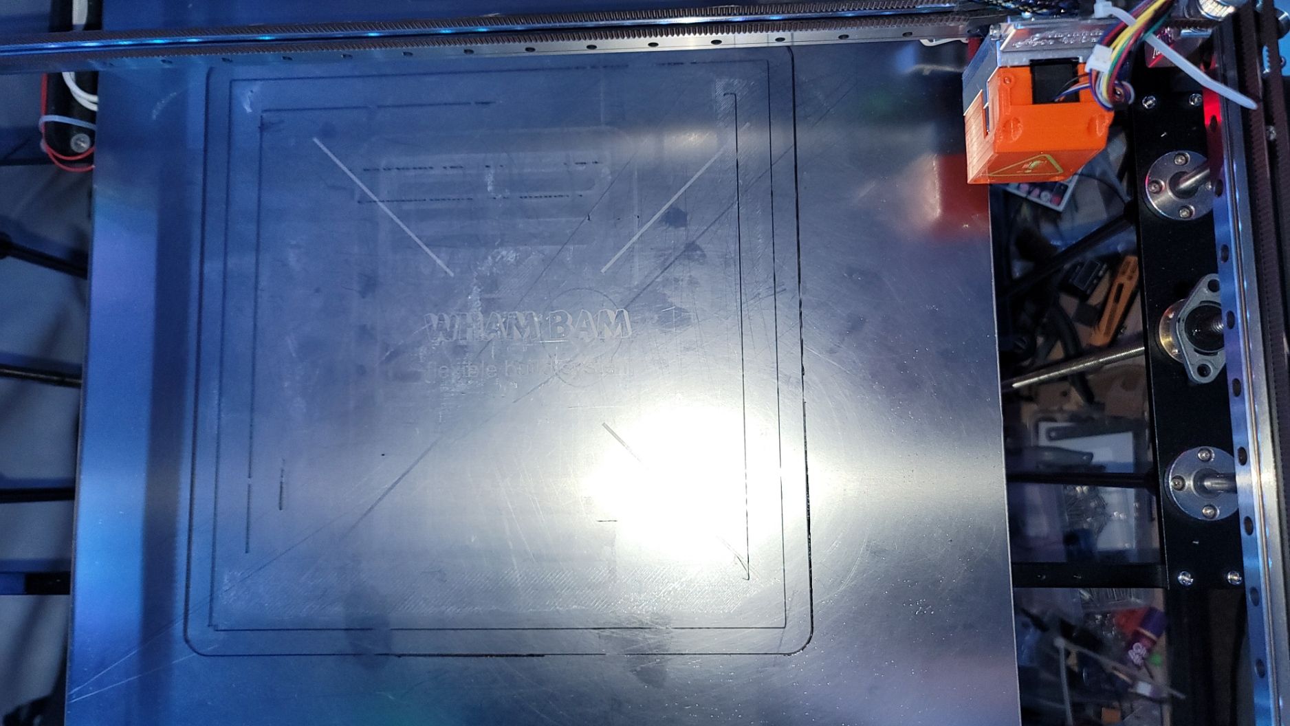
I hadn't been taking pictures of the results but set up a simple single-lined box to test a run of making the first layer and not waste too much filament.
Calibration-Bed-Level-Single-Extrusion-Boxes.stl
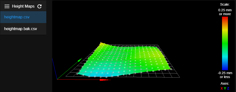
With one of the heightmaps that were generated by the system. You will notice is the image below a lot of areas where the single extrusion lines are missing. This is a result of not getting close enough from what I can tell and as I watched it extrude it would just gather on the nozzle in most cases. Even better, when it actually got something to stick, the slicer thought it best to go back over that line, and low and behold the nozzle would scoop it back up again due to it not barely touching. Here is the result of one such test:
Even after running through my own macro to get the deviations in the bed, I had problems. Now I'm in the process of doing the following:
- Warm the bed and Nozzle to operating temps (Bed: 70°C, Nozzle: 230°C).
- Run G28
- Disable mesh compensation
- Using a feeler gauge manually measure the height of T0 to the bed at my typical 0 location (X200 Y200).
- Move the nozzle to the point on the bed that would normally be measured by the probe and lower it until it just barely touches my feeler gauge.
- Write down the difference in the coordinate on my custom heightmap (feeler gauge is 0.8mm) <feeler gauge height> - <Duet reported Z> = <heightmap value>
Maybe I should have done a smaller height map, but I didn't. It was 3 am and wasn't thinking clearly. I got through the first 3 furthest most Y-Axis rows. I uploaded my slightly modified map and enabled mesh compensation and measured both tools to the feeler gauge at both X200 Y200 and at least one of the points on the map and got approximately a 0 gap. So the method appears to be working, but have a ways to go.
In this image, you can see the right side (bottom of the picture) has a greatly improved first layer. This was using the heightmap I generated using my macro as the basis.

Going forward I need to find my Z-probe tool to make this an easier task and less burning of skin!
-
Just remember that when checking the Z=0 position of your tools it needs to be done at the same XY point you used for setting the Z=0 datum, otherwise bed unevenness may affect the reading.
And mesh compensation should be disabled.
Frederick
-
@fcwilt
I ran a similar test to what you were asking, I think.I turned off mesh compensation and measured at my typical 0 (X200, Y200) location with a feeler gauge (0.8mm) and then moved to a spot that was lower and found that I needed to move the head down. The results were very different from what was recorded either by my manual mesh macro attempts or the systems.
I believe the deviation the probe is finding is accurate, but for some reason is not being applied properly when the tool is engaged and thus having a larger than a normal gap. Not sure about this quite yet.
-
@gamefanatic3d said in Mesh compensation results backwards:
I believe the deviation the probe is finding is accurate, but for some reason is not being applied properly when the tool is engaged and thus having a larger than a normal gap. Not sure about this quite yet.
That is why you need to verify, using the procedure I suggested, that when a tool is positioned at Z=0 the nozzle will be just touching the bed.
It may be simply a question of the Z offset setting for the tool is not quite right.
Frederick
-
@fcwilt
I'm not sure if you saw my comment, but I have performed the procedure. I didn't drag the head across the bed, but rather my feeler gauge. The result was there was a gap at the end as I expected. Rather that was coming from the gantry or the bed height I could not tell you, but there was a variation in the height from when it started to when it finished.I'm not sure if your goal in this was to prove there was variation in the bed or that mesh leveling had been turned off successfully. I know that my bed leveling measures at X180 Y200 and my typical measuring point is X200 Y200, and have tested the gap at both locations with and without the mesh compensation engaged. Each time I get the same result.
If it seems that I'm not providing you the feedback you are looking for, I may just be miss understanding the intended goal or I may not be describing it correctly?
-
@gamefanatic3d said in Mesh compensation results backwards:
@fcwilt
I'm not sure if you saw my comment, but I have performed the procedure. I didn't drag the head across the bed, but rather my feeler gauge. The result was there was a gap at the end as I expected. Rather that was coming from the gantry or the bed height I could not tell you, but there was a variation in the height from when it started to when it finished.I'm not sure if your goal in this was to prove there was variation in the bed or that mesh leveling had been turned off successfully. I know that my bed leveling measures at X180 Y200 and my typical measuring point is X200 Y200, and have tested the gap at both locations with and without the mesh compensation engaged. Each time I get the same result.
If it seems that I'm not providing you the feedback you are looking for, I may just be miss understanding the intended goal or I may not be describing it correctly?
It is likely that I am not making myself clear.
My goal is to verify that the Z probe Z Trigger Height setting is correct and that the Z Offset settings of the tools are correct.
The point of setting the Z=0 datum is to get the logical Z position (what the firmware "thinks" the Z position is) to match the actual Z position.
If the Z probe Z Trigger Height setting is off then the logical Z position will be off.
When you have a single tool printer like mine to verify that the Z probe Z Trigger Height setting is correct you position the nozzle at the exact same XY point you used to set the Z=0 datum and jog the nozzle down until it just touches the bed (or some object of a known thickness) and verify the Z position reported in the DWC is correct.
When you have a multiple tool printer you have the added complication of getting the Tool Z offset setting correct.
It would seem that both the Z probe Z Trigger Height setting and the Tool Z offset setting could lead to the Z logical position being wrong.
Having not worked with a multiple tool printer I don't know how you work that out. Perhaps it is in the Duet documentation.
How do you determine the Tool Z offset setting is correct?
Frederick
Printers: a E3D MS/TC setup and a RatRig Hybrid. Using Duet 3 hardware running 3.4.6
-
@fcwilt said in Mesh compensation results backwards:
What happens if you do this:
- disable mesh compensation
- set the Z=0 datum at a XY point on the bed where the height map suggests it is quite flat
- move tool 0 to that XY point
- move tool 0 to Z=0
- does the nozzle is just touch the bed?
- move tool 1 to that XY point
- move tool 1 to Z=0
- does the nozzle is just touch the bed?
So to respond to this request:
I used an area near the edge of the bed to ensure the feeler gauge isn't being supported by another higher area. My probe is offset from my Nozzles: X= 31.75, Y= -34.4
So when I move to a location I want to test both the probe and the nozzle at the same location I use the above to offset the Duets coordinates for the probe. There is no offset for the Nozzle as those are set by the associated G10 commands and will move to the spot shown by the Duet.
I perform a homing of Z. The process disables mesh compensation, performs the homing, and when done enables mesh compensation.
Step-1 - Prepare Environment
- Heat Bed: 70°C
- T0: 230°C
- T1: 230°C
Step 2 - Probe Height:
- Disable mesh compensation using Duet WebGUI
- G1 X338.25 Y54.4 Z6
- G30 S-1
Result:
8/22/2021, 12:15:34 PM	M98 P"0:/macros/Homing/Bed/Bed_Height_Test"
Stopped at height 0.949 mm
0.049
Step 3 - T0 Height
- T0 (Selected from GUI)
- G1 X370 Y20 Z6
- Using PanelDue Z-5 to achieve Z1.0 height.
- Using Z-0.05 movements after 4 adjustments I'm at Z0.8 and the feeler gauge is now just barely getting a tap when I wiggle it under the tip.
- Using PanelDue Z+5
Step 4 - T1 Height
- T1 (Selected from GUI, system knows to put the T0 back and grab T1)
- G1 X370 Y20 Z6 (Entered it again, but is redundant at this point as my Tools will automatically move to the last point on the bed.)
- Using PanelDue Z-5 to achieve Z1.0 height.
- Using Z-0.05 movements after 5 adjustments I'm at Z0.75 and the feeler gauge is now just barely getting a tap when I wiggle it under the tip.
- Using PanelDue Z+5
It's probably worth noting that my Probe Trigger height is 0.9. So the result noted in Step 2 was the difference from the point measured and my trigger height thus 0.049.
-
@fcwilt said in Mesh compensation results backwards:
@gamefanatic3d said in Mesh compensation results backwards:
My goal is to verify that the Z probe Z Trigger Height setting is correct and that the Z Offset settings of the tools are correct.So I repeated the steps above which are essentially how I get my G10 settings so that I can ensure I've performed as you noted.
Step 1 - Pre environment:
- Bed Temp: 70
- T0 Temp: 230°C
- T1 Temp: 230°C
- Click Home All in WebGUI
- Click Disable Mesh Compensation in WebGUI
Step 2 - Probe Height:
- G1 X168.25 Y234.4 Z6
- G30 S-1
Result:
8/22/2021, 12:47:32 PM	M98 P"0:/macros/Homing/Bed/Bed_Height_Test"
Stopped at height 0.871 mm
-0.029
Step 3 - T0 Height:
- Click Tool-0 in WebGUI
- G1 X200 Y200 Z6
- Using PanelDue move Z-5 (Z=1.0)
- Using Z-0.05 movements, after 3 adjustments I'm at Z0.85, and the feeler gauge is now just barely getting a tap when I wiggle it under the tip.
- Using PanelDue Z+5
Step 4 - T1 Height:
- Click Tool-1 in WebGUI
- G1 X200 Y200 Z6
- Using PanelDue move Z-5 (Z=1.0)
- Using Z-0.05 movements, after 3 adjustments I'm at Z0.85, and the feeler gauge is now just barely getting a tap when I wiggle it under the tip.
- Using PanelDue Z+5
- Click Tool-1 in WebGUI to dock.
Blow on fingers and look for ice and a band-aide...

-
I use this macro when just probing a single point on the bed during the previous tests:
Bed_Height_Test
G1 Z5 F6000 G30 S-1 G1 Z5 F6000 echo (sensors.probes[0].lastStopHeight - sensors.probes[0].triggerHeight) -
@gamefanatic3d said in Mesh compensation results backwards:
G1 X168.25 Y234.4 Z6
Where does those X and Y values come from?
They are different from the X and Y values you use in homez.g when setting the Z=0 Datum.
Given that with a single tool printer the nozzle becomes the reference for checking the Z probe Z Trigger Height setting I'm thinking that to deal with multiple tools the tool 0 Z Offset setting would be 0 so you take the value out of the equation and you can now use the nozzle of that tool as your reference for checking the Z probe Z Trigger Height setting.
Then you set the other tool(s) Z offset based on tool 0.
Frederick
Printers: a E3D MS/TC setup and a RatRig Hybrid. Using Duet 3 hardware running 3.4.6
-
@fcwilt
I think this issue is related to a failing Z-Axis motor. I heard a noise once when letting things sit idle earlier today which resulted in an obvious deviation in the Z-Level. I thought this might be due to the motors going idle and possibly the bed falling. Normally with power off, I don't get more than 0.08 of drift between the two lead screws.However, I was printing just a moment ago and hit the pause button, but when I resumed I heard that noise again when the bed was lifting. So instead of continuing, I paused again and moved the X-Gantry to dead center between the lead screws and measured with my calipers from the top of the rails on either side with an approximately 2.3 mm deviation.
I'm really hoping this is the root cause. They are the original motors operating for over 4 years on my inexpensive starter kit!
I have to take a bit of it apart to get after them so that will have to wait until next weekend, time permitting! -
@fcwilt said in Mesh compensation results backwards:
@gamefanatic3d said in Mesh compensation results backwards:
G1 X168.25 Y234.4 Z6
Where does those X and Y values come from?
That is technically where the Probe - probes when I do my startup. The X/Y noted in the G1 command are where 0 would be at the time, in my case, it's the front of my tool plate (not including the shaft).
The offset of my probe from that location is X31.75 Y-34.4.
When I perform a G1 X200 Y200 the probe is actually probing at X168.25 Y234.4. -
Okay I'm back and after much testing over the past week, I'm convinced there is nothing wrong with my Z-Motors, even though the issue I experienced was real. I believe the Duet may have just been having a moment as I was getting a homing error with negative values when performed the first homez.g after startup. Any future homing would be successful. This appears to have cleared itself up as easily as it came with me doing nothing to the system other than turning it off and back on a few times...
Moving back to the issue at hand here I have mounted a Dial Indicator tool to my system and validated my original statement that the Z-Probing being done and recorded is in fact opposite of what I would expect.
Note: I made the mount for the Dial Indicator such that I could probe with the BLTouch while having the Dial Indicator tool attached. I realize there is a tension that is created as the Dial Indicator gets closer to the end of its measuring.
Probing at a point with the BLTouch will return a positive value to the homing file when it should in fact be a negative value.
My BLTouch trigger value is 0.9.
I validated this by performing the following procedure:
Step 1: Setup
- G28
- Disable Mesh Compensation
- Attach Dial Indicator tool. (Manual process for now)
- G1 X180 Y227 Z6 (Move the BLTouch to a center point on bed)
- G30
- G1 X206.8 Y143.4 Z15 (Move Dial Indicator to same point on the bed with specific height/trigger point)
- Set the Dial Indicator to 0.000
Now I go to a spot on the bed shown on the heightmap that I know to be a low spot (further away from tools)
Step 2: Probing Low
- G1 X328.23 Y224.37 Z6
- M98 P"/macros/Homing/Bed/MyMeshCompStep1"
- G1 X355.03 Y140.77 Z15
The result of BLTouch
8/28/2021, 2:37:40 PM	G1 X355.03 Y140.77 Z15
8/28/2021, 2:37:29 PM	Stopped at height 0.987 mm
-0.085
8/28/2021, 2:37:28 PM	M98 P"/macros/Homing/Bed/MyMeshCompStep1"
Stopped at height 0.983 mm
8/28/2021, 2:36:46 PM	G1 X328.23 Y224.37 Z6
8/28/2021, 2:36:14 PM	G1 X206.8 Y143.4 Z15
8/28/2021, 2:36:03 PM	G30
Dial Indicator: -0.08
I repeat this procedure 3 times in the same spot to validate any potential mechanical issues. Keeping in mind the dial indicator is not as accurate as of the BLTouch and validate the numbers are still roughly the same.
The heightmap.g in this area is showing a positive value in this area. I believe this is due to the BLTouch returning a positive number when subtracting the two probing values which are greater than my trigger (Z-0) value.
IE)
Probe1 returns: 0.918
Probe2 returns: 0.923
The resulting value would be acceptable as it's within 0.005
The value returned should be:-0.0205 = 0.9 - ((0.918+0.923)/2)
But what is recorded in the heightmap is 0.0205
This is my assumption of what is happening based on the heightmaps I am obtaining. I could be missing something here still...
MyMeshCompStep1
var probezHeight = 6 var TravelSpeed = 6000 var probezOne = 0 var probezTwo = 0 while true if iterations = 5 abort "Too many auto calibration attempts" G1 Z{var.probezHeight} F{var.TravelSpeed} G30 S-1 set var.probezOne = sensors.probes[0].lastStopHeight G1 Z{var.probezHeight} F{var.TravelSpeed} G1 Z{var.probezHeight} F{var.TravelSpeed} G30 S-1 set var.probezTwo = sensors.probes[0].lastStopHeight G1 Z{var.probezHeight} F{var.TravelSpeed} if var.probezOne - var.probezTwo <= 0.005 echo sensors.probes[0].triggerHeight-((var.probezOne + var.probezTwo)/2) break -
In your MyMeshCompStep1 file you have
if var.probezOne - var.probezTwo <= 0.005Ignoring any floating point errors:
if var.probezOne = 1.006 and var.probeTwo = 1.000 then var.probezOne - var.probezTwo = 0.006 and the test fails.
if var.probezOne = 1.000 and var.probeTwo = 1.006 then var.probezOne - var.probezTwo = -0.006 and the test succeeds.
In both cases the difference is 0.006.
I don't understand what you are testing for.
Also the number returned by G30 S-1 does not have a fixed relationship to the probe Z Trigger Height setting.
Thanks.
Frederick
Printers: a E3D MS/TC setup and a RatRig Hybrid. Using Duet 3 hardware running 3.4.6
-
@gamefanatic3d said in Mesh compensation results backwards:
I believe the Duet may have just been having a moment as I was getting a homing error with negative values when performed the first homez.g after startup. Any future homing would be successful. This appears to have cleared itself up as easily as it came with me doing nothing to the system other than turning it off and back on a few times...
Have you tried a homez.g without the conditional gcode?