Ok to feed 24V signal directly to Mini5+ IO_5.in?
-
Reading the documentation and the schematic I think the answer is 'yes' but I want to be sure before I fry my board.
Is it safe to feed signal from a 24V inductive probe to the input IO_5.in of the Mini5+? I checked the signal with a voltmeter and it has two states, 0V and +24V.
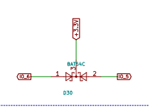
BTW, this is for a Voron V2.4 and the (non Duet specific) manual says to connect a Schottky diode in series to the signal in order to block the 24V. Should I do it just to be on the safe side or not necessary?
-
@zapta see https://duet3d.dozuki.com/Wiki/Duet_3_Mini_5plus_Hardware_overview (emphasis mine)
5 on-board I/O connectors plus 2 input-only connectors for endstop, filament monitor, Z probe, servo or PanelDue connection. Inputs are 30V-tolerant. Further expansion via CAN-connected expansion boards.
-
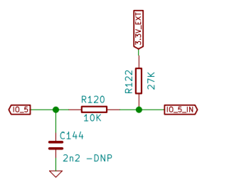
@zapta if it is NPN output, connect it directly. If it's PNP output, use a voltage divider. See https://duet3d.dozuki.com/Wiki/Connecting_a_Z_probe#Section_NPN_output_normally_open_inductive_or_capacitive_sensor and https://duet3d.dozuki.com/Wiki/Connecting_a_Z_probe#Section_PNP_output_normally_open_inductive_or_capacitive_sensor.
Duet WiFi hardware designer and firmware engineer
Please do not ask me for Duet support via PM or email, use the forum
http://www.escher3d.com, https://miscsolutions.wordpress.com -
@dc42, this inductive sensor is an NPN with and internal ~7k pullup resistor to +24V.
@oliof post suggests +30V tolerance but your answer suggests not relying on it for normal operation (e.g. divided for PNP, and for NPN I presume you assume open collector).
Is this the recommended way to approach the +30V tolerance, not relying on it, but it's good that it's there in case something goes wrong?
-
@zapta you can connect an NPN sensor directly. The reason I don't advise connecting a PNP sensor directly is that you may damage something if you connect the sensor output to the +3.3V or +5V pin instead, or if you get a short to one of those pins. A user did that once and wrote off a Duet.
Duet WiFi hardware designer and firmware engineer
Please do not ask me for Duet support via PM or email, use the forum
http://www.escher3d.com, https://miscsolutions.wordpress.com -
Thanks @dc42, your explanation makes sense to me.